Download

1 / 15
150 likes | 244 Views
Explore the input-output relationship of FIR filters, impulse response, and universality of the convolution sum. Learn the steps and examples of linear convolution, as well as frequency selective filters.

E N D
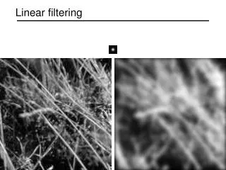
Lecture 18: Linear convolution of Sequences and VectorsSections 2.2.3, 2.3
In the preceding lectures, we examined in detail the response of an FIR filter to two types of inputs: infinite-duration (two-sided) exponentials and periodic sequences. We will now broaden our scope to arbitrary input sequences x[ · ], and discuss the implications of the input-output relationship • We note that the same value for y[n] is obtained if we pad b with infinitely many zero coefficients on both sides, i.e., using the sequence h[ · ] defined instead of b. The input-output relationship above becomes (♠)
The sequence h[ · ] is known as the impulse response of the FIR filter with coefficient vector b. The unit impulse sequence δ[ · ] is defined by and is shown (draw on board) • It is easy to show that x[ · ]= δ[ · ] ⇒ y[ · ]= h[ · ] , • i.e., h[ · ] is the response of the filter to a unit impulse.
The sum in (♠) is known as the (linear) convolution of sequences h = h[ · ] and x = x[ · ]. When computed for all n, it defines a new sequence y = y[ · ]. Symbolically, we write y = h ∗ x • Convolution is commutative in its two arguments. This can be shown by a change in the summation variable, i.e., k’� = n − k: Thus x ∗ h = h ∗ x
FIR filters are characterized by the property that h[ · ] has finite duration, i.e., it takes only a finite number of nonzero values. • Other linear time-invariant systems encountered or used in practice have impulse responses of infinite duration. The convolution sum (♠) is valid for all such systems, i.e., it is a universal input-output relationship in terms of a single characteristic, namely the response of the system to a unit impulse. • To see why h[ · ] can play that role, note that by time invariance, x[ ·− k]= δ[ ·− k] ⇒ y[ ·− k]= h[ ·− k] • for any k. Any input x[ · ] can be expressed as a linear combination of time-shifted impulses, i.e., • By linearity, the output is then given by
For any given n, how to obtain Step 1: time reversal of either signal (e.g., f(k)f(-k) ) Step 2: shift f(-k) by n samples to obtain f(n-k) Step 3: multiply h(k) and f(n-k) for each k and then take the summation over k Steps of Linear Convolution
Example. Let the input to an FIR filter with coefficient vector b = � [2 −1 1 −2]T be given by x[n]= δ[n]+2δ[n − 1] + 3δ[n − 2] − δ[n − 3] • Clearly, the output y[n] equals zero for n< 0 and n ≥ 3+4 = 7, and thus the output sequence has finite duration. The nonzero portion y[0:6] of y[ · ] is computed below.
In general, if h and x are finite-duration sequences with nonzero values limited to the activity intervals 0: K − 1 and 0 : L − 1 respectively, then y = h ∗ x is also a finite-duration sequence whose nonzero values are limited to the (activity) interval 0 : K + L − 2. We can thus define the non-circular convolution of two vectors b and s of length K and L by embedding them into all-zeros sequences, i.e., and computing the convolution h ∗ x at time indices 0 : K + L − 2. In other words, b ∗ s = y[0 : K + L − 2] From the previous example, we have [2 −1 1 −2]T ∗ � [1 2 3 −1]�T = �[2 3 5 −5 0 −7 2]T
Using linearity and/or time invariance, it is easy to show that b ∗ [0i ; s]=[0i ; b ∗ s] b ∗ [s ; 0i]=[b ∗ s ; 0i] b ∗ (αs)= α(b ∗ s) b ∗ (r + s)= b ∗ r + b ∗ s where α is a scalar and 0i is an all-zeros vector of length i.
finite sum of cosines of different frequencies (i.e., multiples of ω) is a smooth curve that has no discontinuities or flat sections. This means that the filter with real-valued frequency response H(ejω) shown below (for ω ∈ (−π, π]) cannot be an FIR filter. • This filter is known as an ideal lowpassfilter of unit gain and zero delay. Ideal frequency-selective filters are characterized by piecewise constant amplitude response and linear phase response (for the filter shown above, the phase response equals zero at all frequencies). Using arguments beyond the scope of this course, it can be shown that such filters cannot be synthesized in practice, whether in FIR form or as any other filter structure.
FIR filters with characteristics which approximate those of ideal filters can be obtained using numerical algorithms. The amplitude (or magnitude) response of a practical lowpassfilter with real coefficients is symmetric about ω = 0 and has the following features: • Its value varies between A(1 − δ) and A(1 + δ) in the passband [0,ωp]; the factor δ is the passband ripple. • It has a maximum value of A in the stopband [ωs,π]; the factor 1/ � is the stopband attenuation. • Its value drops from A(1 − δ) to A � over the transition band [ωp,ωs]; thus the point ωc(cutoff frequency) in the ideal response is approximated by an interval.
The MATLAB filter design and analysis tool (FDATOOL) is a comprehensive interface for designing digital filters of various types. These designs can be also obtained using MATLAB command-line functions. The function FIRPM is used for FIR filters. As an example, b = firpm( M, [0.0 fpfs 0.5]*2, [A A 0 0] ); produces a lowpass FIR filter with coefficient vector b of length M + 1. The passband and stopband edges are ωp =2πfp and ωs =2πfs, respectively. The ideal passband and stopband gains are A and 0, respectively. (Additional parameters can be inserted to control the relative amounts of passband ripple and stopband attenuation.) Your task: Run b = firpm( 36, [0.0 0.12 0.15 0.5]*2, [1 1 0 0] ); and plot the amplitude and phase response of the filter. Determine the passband ripple δ and stopband attenuation 1/�.