Download
1 / 59

E N D
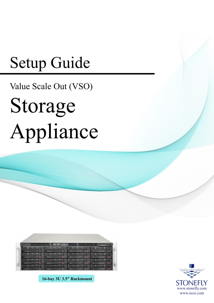
Setup Guide Value Scale Out (VSO) Storage Appliance 16-bay 3U 3.5” Rackmount www.stonefly.com www.iscsi.com
Copyright 2006, 2007, 2008, 2009, 2010, 2011, 2012, 2013, 2014, 2015, 2016, 2017, 2018 StoneFly, Inc. All rights are reserved. No part of this document may be photocopied or reproduced without the prior written consent of StoneFly. The information contained in this document is subject to change without notice. StoneFly shall not be liable for errors contained herein or for consequential damages in connection with the furnishing, performance, or use of this material. StoneFly, the StoneFly logo, Storage Concentrator, Integrated Storage Concentrator, ISC, Modular Storage Concentrator, StoneFly Backup Advantage, StoneFusion, StoneFly Replicator CDP, ValueSAN, Unified Scale Out, USO, Twin Scale Out, TSO, Unified Storage & Server, USS, Unified Deduplicated Storage, UDS, Unified Encrypted Storage, UES, OptiSAN, StoneFly Voyager, StoneFly Mirroring, Storage Concentrator Virtual Machine, SCVM, Software-Defined Unified Storage and SDUS are property of StoneFly, Inc., a wholly owned subsidiary of Dynamic Network Factory, Inc. Other brands and their products are trademarks or registered trademarks of their respective holders. Last update Date: 7/2019
StoneFly VSO Appliance Setup Guide Table of Contents Contents Introduction .................................................................................................. 7 1.1 Conventions .................................................................................................. 8 1.2 Product Overview .......................................................................................... 10 2.1. Theory of Operation ....................................................................................... 13 2.2. Installation .................................................................................................. 13 2.3 Safety Information ......................................................................................... 16 2.4 Product Registration ....................................................................................... 16 2.5 Contacting StoneFly for Help ............................................................................. 17 2.6 Setting Up the VSO ........................................................................................... 19 3.1 V8.0.3x © StoneFly, Inc. 2018 Page IV
StoneFly VSO Appliance Setup Guide Introduction Chapter-1: Introduction
StoneFly VSO Appliance Setup Guide 1.1Introduction This guide provides the information needed to perform the out-of-the-box setup and configuration tasks for the StoneFly VSO storage appliance. After completing the steps in this guide, proceed to the Storage Concentrator User’s Guide. Refer to “Chapter 2 – Administrative Interface” for information on how to efficiently and effectively manage data storage, data protection, and data delivery on your network. This setup guide is intended to be used by network administrators and assumes a basic understanding of: Introduction Local Area Networks (LAN) Ethernet and Ethernet-switching concepts Network Attached Storage (NAS) 1.1.1 Other Resources Other useful information regarding the setup and use of your VSO can be found in the following places: StoneFly Storage Concentrator User’s Guide The StoneFly Web site: www.stonefly.com The VSO Online Help in the administrative interface (following initial setup) Page 7 V8.0.3x © StoneFly, Inc. | All rights reserved
StoneFly VSO Appliance Setup Guide 1.2 The following table lists the conventions used throughout this Guide. 1.2.1 Icons Icon Type Note Introduction Conventions Description Special instructions or information Warning Risk of system damage or a loss of data Page 8 V8.0.3x © StoneFly, Inc. | All rights reserved
StoneFly VSO Appliance Setup Guide Overview Chapter-2: Overview V8.0.3x Page 9 © StoneFly, Inc. | All rights reserved
Overview StoneFly VSO Appliance Setup Guide 2.1. Based on the StoneFusion operating system, the VSO™ delivers target volumes to hosts over TCP connections in an Ethernet network. VSO™ also offers Network Attached Storage (NAS) which allows multiple hosts/users share files. Configuring and managing the VSO™ is accomplished using a browser-based graphical user interface (GUI) resident in the VSO™. Storage resources are connected to the VSO™ through either internal drives or coming from one or more expansion boxes connected to the external SAS port (4, 6, 12 16, and 24-bay VSO appliances only). The system administrator uses the GUI to allocate blocks of storage to create the iSCSI target volumes and authorizes their use by individual host systems. Product Overview Figure 1: VSO 16-bay Model (without front bezel) The VSO comes in four standard configurations: VSO-40T/VSO-40R: 4-bay model features maximum of 4 SATA drives or SSDs VSO-60R: 6-bay model features maximum of 6 SATA drives or SSDs VSO-120R: 12-bay model features maximum of 12 SAS drives or SSDs VSO-160R: 16-bay model features maximum of 16 SAS drives or SSDs VSO-240R: 24-bay model features maximum of 24 SAS drives or SSDs The VSO comes pre-configured in multiple RAID sets with hot spare drives. To change the RAID configuration settings you must use the RAID configuration utility for VSO. Please consult the RAID Controller Manual included on the documents CD. The VSO features a management port, one or two dual-port Gigabit Ethernet (GbE) cards for data I/O, and a SAS Raid HBA that drives internal drives and also has an external port for connection to expansion boxes. V8.0.3x Page 10 © StoneFly, Inc. | All rights reserved
Overview StoneFly VSO Appliance Setup Guide 2.1.1 The following table details additional features of the VSO. VSO Features and Benefits Feature Benefits IP network-based SAN intelligence based on StoneFusion OS Less expensive to install and operate Universal connectivity on IP networks Uses existing network No retraining of personnel on new technologies Lowers total cost of ownership No distance limitations for IP networks Storage Provisioning Add, delete, or expand volumes easily Maximizes utilization of storage resources Responds to changes quickly Mirroring Supports both local and remote, synchronous and asynchronous mirroring with StoneFly Reflection™ and StoneFly Replicator® CDP software Disk-to-Disk backup Simultaneous backup streams from multiple servers for faster, more reliable backups Nearly instantaneous restores from disk HTML-based GUI management Centralized storage management, control and monitoring of provisioned storage pools Access and administer changes from a browser anywhere at anytime Secure access (https) Easy and intuitive to use Security Access Control Lists designate which storage resources are accessible to which hosts and specify read/write, read only, or no access privileges CHAP (Challenge Handshake Authentication Protocol) supports passwords at the host or volume level Expandable storage capacity with additional storage resources (optional) Works with SAS JBODs containing SATA or SAS drives. Access local and remote copies of user High availability V8.0.3x Page 11 © StoneFly, Inc. | All rights reserved
Overview StoneFly VSO Appliance Setup Guide configuration data Object storage resources Integrated cloud connection to Microsoft Azure Blob Storage, Amazon AWS S3 and/or compatible AWS S3 storage V8.0.3x Page 12 © StoneFly, Inc. | All rights reserved
StoneFly VSO Appliance Setup Guide 2.2. The StoneFly VSO™ is the mediator between hosts and storage devices in an IP network. IP- based Storage Area Networks (IP SANs) use the iSCSI protocol over an Ethernet and TCP/IP network. VSO offers Network Attached Storage (NAS), which allows multiple host/users share files over an Ethernet network. Each server, host, or user that needs access to the SAN storage devices must implement the iSCSI protocol over an Ethernet and TCP/IP network. 2.2.1 Network Attached Storage (NAS) Network Attached Storage (NAS) is a storage technology that allows users to create shared volumes that can be accessed by one or more users. The difference between iSCSI volumes and NAS volumes are that NAS volumes (NAS shares) can be accessed by more than one user/server, but iSCSI volumes in general can only be accessed by one server. 2.2.2 Back-End Storage One of the major benefits of the VSO appliance is the ability to expand using optional back- end storage. Back-end storage can use SAS JBODs (Just a Bunch of Disks) that can house SATA or SAS drives. The storage devices connect directly to the back of the VSO SAS port. The VSO mediates requests from host servers for storage resources, just as servers mediate storage requests from end-user clients on the network. Therefore, it is prudent to set up the VSO on a dedicated Gigabit Ethernet storage network that is operating independently of the LAN that mediates traffic between clients and hosts. It is recommended that you setup a dedicated subnet running on a 10/100/1000 network to prevent management of the NAS from interfering with data I/O traffic. 2.3 Installation 2.3.1. Requirements Overview Theory of Operation The following minimum network system requirements must be met before attempting to install the VSO: 1.Connectivity to an Ethernet network (10/100/1000) 2.Storage resources (devices) are either internal drives or coming from expansion box(es) connected to an external SAS port 3.Computer must have one of the following browsers: A.FireFox 1.0 or later or Netscape 4.7 or later (Windows PC or Linux) B.Internet Explorer 5.0 or later (Windows PC only) Page 13 V8.0.3x © StoneFly, Inc. | All rights reserved
StoneFly VSO Appliance Setup Guide 2.3.2. To set up a simple IP SAN using a VSO, use the steps that follow: 1.Connect your SAS JBOD storage (if you have any) to the back of the VSO (optional). 2.Install the VSO using the steps that follow: A. Connect the VSO to the switch. If you are using the multi-port GbE connections, you can plug in all or some of the connections. Only by plugging in more than one connection will you have automatic Adaptive Load Balancing. B. Connect the VSO to power using the power cord connection. Overview Setting Up a Simple IP NAS Using an VSO 3.Connect a laptop or other local computer to the Management port using a cross- over cable either directly or through an Ethernet switch. 4.Set up the IP network so that the Management port is on a different subnet than the main network. 5.Configure the VSO and provision your storage volumes. 6.Install iSCSI initiators composed of either iSCSI adapter cards or iSCSI HBAs into the servers or use iSCSI software initiators for standard network interface cards (NICs) installed in the servers. 7.Connect the servers to the Gigabit Ethernet switch. 8.Set up the initiators on the servers to recognize the provisioned storage volumes and configure security settings. Page 14 V8.0.3x © StoneFly, Inc. | All rights reserved
StoneFly VSO Appliance Setup Guide Overview Figure 2: A Typical Configuration of VSO VSO NAS and VSO SAN require different licenses. VSO NAS does not have iSCSI by default. iSCSI protocol needs the SAN license. For more information about licenses, contact StoneFly support. Page 15 V8.0.3x © StoneFly, Inc. | All rights reserved
StoneFly VSO Appliance Setup Guide 2.4 Please review the following safety information completely before installing your VSO. 2.4.1 Environmental Requirements for power and network availability must be taken into consideration when planning where to place your VSO. The space should have well regulated temperature and humidity and should be relatively free of dust and other contaminants. The list below provides specifics on the environmental requirements: Overview Safety Information 1.Operating temperature: +50 F to +95 F (10 C to 35 C). 2.Altitude: -50 to 10,000 feet (-16 to 3048 meters). 3.Relative humidity: 8% to 80% (non-condensing). 2.4.2 Compliance FCC 47 CFR Part 15, Class A CSA C1088, Class A UL 60950; CUL 60950 CE Mark (EN 455022, Class A/EN 455024) 2.5 Product Registration To initiate StoneFly customer service for your product, you must first register your VSO. Go to the StoneFly web site at https://stonefly.com/support or mail in the registration card that was included with your VSO. Please have the following information available when registering your VSO: Model Number: Serial Number: D500_ _ __ Page 16 V8.0.3x © StoneFly, Inc. | All rights reserved
StoneFly VSO Appliance Setup Guide 2.6 Please have the following information available when contacting StoneFly technical support for assistance: Overview Contacting StoneFly for Help Model Number: Serial Number: D500_ _ _ _ Software Version: Initiators: Storage: Storage Serial Number(s): To contact StoneFly, call 510.265.1616 and select support from the menu or go to the StoneFly support page at https://www.stonefly.com/support and fill out the contact form. Page 17 V8.0.3x © StoneFly, Inc. | All rights reserved
StoneFly VSO Appliance Setup Guide Initial Installation Chapter-3: Initial Installation Page 18 V8.0.3x © StoneFly, Inc. | All rights reserved
StoneFly VSO Appliance Setup Guide Initial Installation 3.1 Setting Up the VSO This section will provide step-by-step instructions for initial system configuration and hardware setup of the VSO. 3.1.1 Unpacking Unpack the hardware from the box. You will find: 1.The VSO Appliance 2.The front bezel for the VSO 3.Power cords 4.A product registration card for the VSO 5.A documentation CD with the StoneFly Storage Concentrator User’s Guide and all other documentation 6.A StoneFusion Operating System CD for system recovery 3.1.2 Mounting Equipment Mounting rails for the VSO are included in the package. One set of rails is required for rack mounting each VSO. This guide provides information on installing the StoneFly VSO chassis into a rack unit with the rails provided. There are a variety of rack/cabinet units on the market, which may mean the assembly procedure will differ slightly. You should also refer to the installation instructions that came with the rack unit you are using. Note: These rails fit a rack between 26.5” and 36.4”. Identifying the Section of the Rack Rails The chassis package includes two rail assemblies, one designed and labeled for each side of the chassis. Each assembly consists of an inner rail that secures directly to the chassis, and an outer rail that secures to the rack. The outer rail has two sections that can slide and adjust to fit your rack depth. Page 19 V8.0.3x © StoneFly, Inc. | All rights reserved
StoneFly VSO Appliance Setup Guide Initial Installation Identifying the Rails Releasing the Inner Rail Each inner rail has a locking latch. This latch prevents the server from coming completely out of the rack when the chassis is pulled out for servicing. To mount the rail onto the chassis, first release the inner rail from the outer rails. Releasing Inner Rail from the Outer Rails •Pull the inner rail out of the outer rail until it is fully extended. •Press the locking tab down to release the inner rail. •Pull the inner rail all the way out. Extending and Releasing the Inner Rail Page 20 V8.0.3x © StoneFly, Inc. | All rights reserved
StoneFly VSO Appliance Setup Guide Installing the Inner Rails on the Chassis Installing the Inner Rails Initial Installation •Identify the left and right inner rails. They are labeled. •Place the inner rail firmly against the side of the chassis, aligning the hooks on the side of the chassis with the holes on the inner rail. •Slide the inner rail forward toward the front of the chassis until the quick release bracket snaps into place, secure the rail to the chassis. •Optionally, you can further secure the inner rail to the chassis with screws. Installing the Inner Rails Inner Rails Installed on the Chassis Page 21 V8.0.3x © StoneFly, Inc. | All rights reserved
StoneFly VSO Appliance Setup Guide Installing the Outer Rails onto the Rack Installing the Outer Rails Initial Installation •Press upward on the locking tab at the rear end of the middle rail. •Push the middle rail back into the outer rail. •Hang the hooks on the front of the outer rail onto the square holes on the front of the rack. If desired, use screws to secure the outer rails to the rack. •Pull out the rear of the outer rail, adjusting the length until it just fits within the posts of the rack. •Hang the hooks of the rear section of the outer rail onto the square holes on the rear of the rack. Take care that the proper holes are used so the rails are leveled. If desired, use screws to secure the rear of the outer rail to the rear of the rack. •Repeat for the other outer rail. Extending and Mounting the Outer Rails The rack stabilizing mechanism must be in place, or the rack must be bolted to the floor before you slide the unit out for servicing. Failure to stabilize the rack can cause the rack to tip over. Do not use a two post “telco” type rack. Page 22 V8.0.3x © StoneFly, Inc. | All rights reserved
StoneFly VSO Appliance Setup Guide Sliding the Chassis onto the Rack Rails Installing the Chassis into a Rack • Align the inner rails of the chassis with the outer rails on the rack. • Slide the inner rails into the outer rails, keeping the pressure even on both sides. When the chassis has been pushed completely into the rack, it should click into the locked position. • Optionally, screws may be used to hold the front of the chassis to the rack. Initial Installation Warning: Mounting the system into the rack requires at least two people to support the chassis during installation. Please follow safety recommendations printed on the rails. Installing into a Rack Note: The figure above is for illustrative purposes only. Always install servers to the bottom of the rack first. Caution: Do not pick up the server with the front handles. They are designed to pull the system from a rack only. Page 23 V8.0.3x © StoneFly, Inc. | All rights reserved
StoneFly VSO Appliance Setup Guide 3.1.3 Cabling the Storage Appliance Systems vary. When attaching cables follow the labeling on the rear of your unit for the various network ports (iSCSI/NAS for data, FC SAN for data, IPMI and System Management ports for Management). The data ports should be connected to a different network than the management port. Connect a keyboard and monitor (or KVM) to the USB and VGA ports for the initial configuration. Lastly, connect both power cords. Initial Installation SAS Extension Management Ports 10Gb Data Port RAID Management Port (Do not connect) HDMI 2.0 1Gb Data Port VSO Back Panel 3.1.4 Configuring the Network Settings for the IPMI KVM This section applies to storage appliances with IPMI support The Intelligent Platform Management Interface (IPMI) KVM configuration allows for Remote Management and Power Control of the StoneFly VSO system. This configuration is optional to perform, but recommended. To configure the IPMI module, connect a Keyboard and Monitor to the System. Power on the system and press the Delete key to enter the BIOS setup. Page 24 V8.0.3x © StoneFly, Inc. | All rights reserved
StoneFly VSO Appliance Setup Guide Initial Installation On the BIOS screen, navigate to the Advanced tab and select IPMI Configuration. The IPMI configuration screen will be displayed. Select Set LAN Configuration. The network settings will be displayed. Page 25 V8.0.3x © StoneFly, Inc. | All rights reserved
StoneFly VSO Appliance Setup Guide Initial Installation Adjust the following settings as needed: IP Address Source IP Address Subnet Mask Default Gateway Update LAN Settings Yes Choose “Static” Must be on the same subnet as the VSO’s Management port IP Same as the VSO’s Management port Same as the VSO’s Management port Press the F10 key to save the changes and exit. Note: Power cycle the system for the new IPMI IP Address to take effect. Open a web browser on a system running on the same subnet as the VSO’s IPMI and Page 26 V8.0.3x © StoneFly, Inc. | All rights reserved
StoneFly VSO Appliance Setup Guide navigate to the IP address you configured in the last section. Initial Installation Enter the following information in the login screen: •Username: ADMIN •Password: ADMIN Select the Remote Control tab to access the system console. Page 27 V8.0.3x © StoneFly, Inc. | All rights reserved
StoneFly VSO Appliance Setup Guide Initial Installation Select Launch Console to open the system console. The console screen will appear as shown above. Page 28 V8.0.3x © StoneFly, Inc. | All rights reserved
StoneFly VSO Appliance Setup Guide 3.1.5 Initial Installation Configuring the Network Settings for the VSO Management Port The VSO’s management port is preconfigured with the default IP address of 192.168.0.254. This must be changed to a valid IP address for your LAN network. Using the remote console you loaded in the previous section: Press Enter to display the login prompt. At the User ID prompt type console and hit Enter. At the password prompt type coni100o and hit Enter. Note that the User ID and password are case sensitive. Using the Storage Concentrator Service menu, enter 2 to select Network. The current network configuration settings will appear as shown below: Page 29 V8.0.3x © StoneFly, Inc. | All rights reserved
StoneFly VSO Appliance Setup Guide Initial Installation Configure all of the network settings to those appropriate for your LAN network by selecting each of the numbered fields. When finished, enter s option to Save Changes, then completely exit the CLI using the q option for Logout. The login prompt should reappear. Browser access to the VSO’s management GUI is blocked while the CLI menu is active. Also note that there can be a short delay before the web GUI becomes available once the CLI is closed. At this point, it should be possible to login to the web GUI for the StoneFly VSO appliance by browsing to the management IP address that you just configured in the last step. Once logged in, you should configure the SAN data network settings. Page 30 V8.0.3x © StoneFly, Inc. | All rights reserved
StoneFly VSO Appliance Setup Guide 3.1.6 Initial Installation Initial Configuration of StoneFly StoneFusion™ Figure 8: StoneFusion Login Screen 1. In the User ID field type: admin 2. In the Password field type: M@n4g1ng 3. Click Submit. The Home Page screen will appear. 4. Click System. 5. Click Admin. 6. Click Auto Save. The Auto Save screen will appear. Page 31 V8.0.3x © StoneFly, Inc. | All rights reserved
StoneFly VSO Appliance Setup Guide Initial Installation Figure 9: StoneFusion System Auto Save Screen 7. Select method(s) of saving the database. A USB Flash must be inserted into the USB port prior to Enabling. Checkmark Enable Auto Save to Local Device and select USB Flash Disk from the dropdown menu. Click Submit. For Auto Save to Remote FTP Server create a directory for each Storage Concentrator. Fill in the IP Address, User Name, Password and directory. Select Passive or Non Passive and click Submit. Both methods can be used, but at least one should be configured to ensure recovery if needed. 8. Navigate to Admin > General. The system admin screen will appear. Page 32 V8.0.3x © StoneFly, Inc. | All rights reserved
StoneFly VSO Appliance Setup Guide Initial Installation Figure 10: StoneFusion System Admin Screen 9. Enter a system name for the VSO. 10. Enter the number of log records for the database in the Max number of logs field. The default number of log records is 2000, which is sufficient for most installations. 11. Click Submit. 12. Navigate to Network > Data Port. The Local iSCSI Data Port Settings screen will appear with the current system (factory) settings. Most fields are blank. Page 33 V8.0.3x © StoneFly, Inc. | All rights reserved
StoneFly VSO Appliance Setup Guide Initial Installation Figure 11: StoneFusion Local iSCSI Data Port Settings Screen 13. Enter the IP Address for the Local iSCSI Data Port. 19. Enter the NetMask setting for the Local iSCSI Data Port. 20. Click Submit. 21. Click OK to continue when the confirmation dialog box appears. The VSO automatically configures the Network and Broadcast settings based on the IP address and Netmask settings. Click on the Advanced: Network/Broadcast link to view or modify the Network and Broadcast settings. For more information, see “Chapter 2: Administrative Interface” in the Storage Concentrator User’s Guide. 22. Review the status of all SAN Network Interfaces to select which ports will be used. It is not necessary to select all available ports. All ports selected must have cables attached to them to maintain the proper cluster configuration and operation. The Id button is used to flash the link light on a specific port. Select a port by clicking on the box in the Bond column. Changes are not enforced until the next reboot. At first power up a default configuration is presented. Changing the default settings requires a reboot of the Storage Concentrator. Navigate to the System > Admin > General screen and click on Reboot. If no changes are desired continue to the next step to configure the Management Port. 23. Click on Management Port. The Management Port Settings screen will appear. Page 34 V8.0.3x © StoneFly, Inc. | All rights reserved
StoneFly VSO Appliance Setup Guide Initial Installation Figure 12: StoneFusion Management Port Settings Screen 24. Enter the Default Gateway setting. 25. Enter the IP Address for the Management port. 26. Enter the NetMask setting for the Management port. It is not necessary to select a Management Port as on the Local iSCSI Port screen. There is only one port assigned for this purpose. The VSO automatically configures the Network and Broadcast settings based on the IP address and Netmask settings. Click on the Advanced: Network/Broadcast link to view or modify the Network and Broadcast settings. For more information refer to “Chapter 2: Administrative Interface” in the Storage Concentrator User’s Guide. Changing the IP address of the Management port will cause your browser to lose its connection to the VSO. To access the VSO, set your browser’s URL to point to the new IP address. 27. Click Submit. The following popups will appear. Depending on the speed of your browser connection, you may not see this screen. Your changes will still take effect, however you will need to manually set your browser’s URL to point to the new IP address. Page 35 V8.0.3x © StoneFly, Inc. | All rights reserved
StoneFly VSO Appliance Setup Guide Initial Installation Figure 13: System Management GbE Port Change Screen 28. Click on OK on each popup screen to continue. 29. Click on the new IP address to confirm the change to the Management Port setting. Page 36 V8.0.3x © StoneFly, Inc. | All rights reserved
StoneFly VSO Appliance Setup Guide Initial Installation 3.1.7 Setting Up Routing To access a host on other networks, routing information to those networks must be configured in the System Management Network Routing screen. A route must be added if the host has a network setting that is different from the one listed in the iSCSI Host GbE Port Settings screen. For example, if the VSO network setting is 26.34.128.50 and the host network setting is 106.39.212.6, a route to the host must be configured. To configure the routing information, use the steps that follow: 1. Navigate to System > Network > Routing. The Routing screen will appear. Figure 14:StoneFusion System Management Network Routing Screen 2. In the Add New Route fields, enter the Network, Netmask, and Gateway settings for the new route. 3. Click the Add check box. 4. Click Submit. 5. Navigate to Admin > General. The System Admin screen will appear. The VSO must be rebooted for the new routing settings to be recognized. 6. Click Reboot. Page 37 V8.0.3x © StoneFly, Inc. | All rights reserved
StoneFly VSO Appliance Setup Guide Initial Installation 3.1.8 Confirming Setup It is important to confirm that the VSO is configured properly to communicate on your network before completing the configuration process covered in the “Administrative Interface” chapter of the Storage Concentrator User’s Guide. To confirm that the VSO is configured properly, do the following: 1. Launch your web browser. In the URL address field, type the IP address you set up for the Management GbE port during the configuration process. Be sure to include https:// in the address. The browser will display an alert regarding the security certificate for the site. This occurs because the IP address for the VSO was changed from the factory default to one appropriate for your network. 2. Follow the screen prompts to accept the certificate. The number of screens will vary depending on which browser you are using. When the security certificate is accepted, the VSO administrative interface login screen will appear. 3. Click on System and then Network to confirm the network settings. 4. Click on Data Port and confirm the settings. 5. Click on Management Port and confirm the settings. 6. Click on Routing and confirm the settings. 3.1.9 Steps to Complete Before Setting Up the System: 1.Read the Release Notes thoroughly. These can be found in your documentation CD. 2.Verify that your Host Initiators are at the most current revision levels. For example, if you are using the Microsoft Windows iSCSI Initiator, obtain the latest version from Microsoft. 3.Refer to Appendix 7: System Considerations, in the StoneFly Storage Concentrator User’s Guide and make sure that you set up your servers according to the instructions in that section before connecting or using your StoneFly Appliance. CAUTION: Not setting up your systems according to those instructions will cause timeouts and SAN disconnections. Page 38 V8.0.3x © StoneFly, Inc. | All rights reserved
StoneFly VSO Appliance Setup Guide Initial Installation 3.1.10 Attaching and Removing the Front Bezel Attach the front bezel after initial installation is completed. This will help prevent damage to the drives during everyday use. The cover snaps on and off easily and can be removed as needed. To install the cover, gently press to snap the cover into place. To remove the cover, gently pull the cover towards you to remove it from the front panel. Page 39 V8.0.3x © StoneFly, Inc. | All rights reserved
Troubleshooting StoneFly VSO Appliance Setup Guide Chapter-4: Troubleshooting V8.0.3x Page 40 © StoneFly, Inc. | All rights reserved
Troubleshooting StoneFly VSO Appliance Setup Guide Refer to the following table for helpful hints on solving some of the most common problems. If you cannot find a resolution to your problem here, contact StoneFly. Call 510.265.1616 and select support from the menu. Problem Possible cause Solution The VSO administrative interface is not accessible from the computer. Ensure that the computer is running a supported browser and is on the same network or subnet as the VSO. The computer is not on the network. An incorrect IP address was typed in the address line of the browser. Try the following: •Verify and retype the IP address in the browser. •Make sure the IP address begins with https. The IP address does not begin with http. Incorrect network settings were entered during installation. For the correct settings, see “Configuring the Network Settings” on page 26. The network cable is not properly connected to the computer or the VSO. Try the following: •Check all network cable connections. •Make sure the network cable is not damaged. The VSO cannot be configured using the factory- supplied IP address. The cable is not a network crossover cable. Use a network crossover cable. Page 41 V8.0.3x © StoneFly, Inc. | All rights reserved
Troubleshooting StoneFly VSO Appliance Setup Guide The network crossover cable is plugged into the incorrect port on the back of the VSO. Plug the network crossover cable into the Management Gigabit Ethernet (GbE) port on the back of the VSO. See, “Configuring the Network Settings” on page 26. The computer is not configured to communicate in the 192.168.0.0 network. Configure the computer to communicate in the 192.168.0.0 network. The administrative interface resides on the Storage Concentrator. It is run from a network computer via a browser which can access the network where the Storage Concentrator is located. Supported browsers include: •Netscape 4.7 or later (Windows PC and Linux) •Internet Explorer 5.0 or later (Windows PC only) •Mozilla Firefox To access the administrative interface, use the steps that follow: Launch your web browser. 1. Type the IP address for the Management Port of the Storage Concentrator in the address field of the browser. 2. The address field in the browser must include https:// to access the administrative interface. Page 42 V8.0.3x © StoneFly, Inc. | All rights reserved
Glossary StoneFly VSO Appliance Setup Guide Appendix-1: Glossary V8.0.3x Page 43 © StoneFly, Inc. | All rights reserved
Glossary StoneFly VSO Appliance Setup Guide Access Control List (ACL) A list that controls which hosts have access to which volumes. When a host attempts to log in, the Storage Concentrator requests authorization and allows access based on the list. Access Path The route used by a computer to communicate with a storage device. The path accesses the host bus adapter, host storage interconnection controller and logical unit. Some configurations support multiple access paths to a single device. Administrative Interface The graphical administrative interface is accessed from a computer on the network via a web browser. The following functions are available through the interface: Storage Concentrator discovery, physical resource management, storage pool management, logical volume management, target management, Access Control List management (ACL), system management, session management. Adaptive Load Balancing A feature that allows for more than one networking path providing port FailOver protection, as well as increased bandwidth. If one port goes down, the other port automatically accepts the additional load. There is no interruption in server operation, and a network alert is generated to inform IT staff of the problem. Application Programming Interface (API) The interface used by an application program to request services; usually denotes interfaces between applications and the software components that comprise the operating environment (e.g., operating system, file system, volume manager, and device drivers). Array or Array Configuration A storage array, i.e., a disk array or RAID array. 1.Assignment of the disks and operating parameters for a disk array. Disk array configuration includes designating the member disks or extents of the array and the order in which they are to be used, as well as setting parameters such as stripe depth, RAID model, cache allowance, spare disk assignments. V8.0.3x © StoneFly, Inc. | All rights reserved Page 44
Glossary StoneFly VSO Appliance Setup Guide 2.The arrangement of disks and operating parameters that result from such an assignment. Asynchronous I/O Operation An I/O operation whose initiator does not await its completion before proceeding with other work. Asynchronous I/O operations enable an initiator to have multiple concurrent I/O operations in progress. Asynchronous Mirroring Transactions that maintain synchronization for logical volumes occur in a batch rather than real-time mode. An asynchronous mirroring is desired when mirrored logical volumes are separated by distance in order to reduce the effects of distance- induced latency. It is also desirable to use Asynchronous Mirroring or replication to reduce the bandwidth requirements of the network connection. Backup 1.(noun) A collection of data stored on non-volatile (usually removable) storage media for purposes of recovery in case the original copy of data is lost or becomes inaccessible. The data is also called the backup copy. To be useful for recovery, a backup must be made by copying the source data image when it is in a consistent state. 2.(verb) The act of creating a backup. Campus Mirrors Mirror images that are behind the Secondary Storage Concentrator CHAP CHAP (Challenge Handshake Authentication Protocol) allows you to set a Password or “Secret” for as a gatekeeper for communication between a host initiator and a volume. Clusters You must have at least two Storage Concentrators to implement FailOver on an IP Storage. Multiple Storage Concentrators are known as a cluster. In a clustered pair there will be one Primary and one Secondary Storage Concentrator. A cluster V8.0.3x © StoneFly, Inc. | All rights reserved Page 45
Glossary StoneFly VSO Appliance Setup Guide appears as a single entity to hosts on the network. Concatenation A logical joining of two series of data, usually represented by the symbol "|". In data communications, two or more data are often concatenated to provide a unique name or reference (e.g., S_ID | X_ID). Volume managers concatenate disk address spaces to present a single larger address space. Configuration 1.The process of installing or removing hardware or software components required for a system or subsystem to function. 2.Assignment of the operating parameters of a system, subsystem, or device. For example, disk array configuration includes designating the member disks or extents for the array, as well as setting parameters such as stripe depth, RAID model, and cache allowance. 3.The collection of hardware and software components and operating parameters for an operating system. Controller The control logic in a storage subsystem that performs command transformation and routing, aggregation (RAID, mirroring, striping, or other aggregation), high- level error recovery, and performance optimization for multiple storage devices. Controller-based Array A disk array whose control software executes in a disk subsystem controller. The member disks of a controller-based array are necessarily part of the same disk subsystem that includes the controller. Database Management System (DBMS) A set of computer programs with a user and/or programming interface that supports defining the format of a database, and creating and accessing the data. A database management system removes the need for a user or program to manage low-level database storage. It also provides security and assures the integrity of the data it contains. Database management systems may be relational (table-oriented) or object- oriented. Data Transfer Rate V8.0.3x © StoneFly, Inc. | All rights reserved Page 46
Glossary StoneFly VSO Appliance Setup Guide The amount of data per unit time moved across an I/O bus while executing an I/O load. For any I/O load, the data transfer capacity of an I/O subsystem is limited by its data transfer rate. For disk subsystem I/O, data transfer rate is usually expressed in MB/second (millions of bytes per second where 1 million is 10 ). 6 Detach Image Detaching an image allows it to be mounted and used by other software applications. The most common usage is to make a backup copy of the detached image. The detached image retains the mirror volume information and can be rejoined at any time. Disk Array A set of disks from one or more commonly accessible disk subsystems, combined with a body of control software. The control software presents the storage capacity of the disk to hosts as one or more logical disks. When it runs on a disk controller, control software is often called firmware or microcode. Control software that runs on a host computer is usually called a volume manager. A disk subsystem which includes control software with the capability to organize disks as disk arrays. Disk Array Subsystem Disk Drive A non-volatile, randomly addressable, writable data storage device. Subdivision of a disk drive, disk array, or RAID array. Disk Partitions Distributed Lock Manager (DLM) Software, hardware or a combination of hardware and software that prevents multiple writers from altering a data element simultaneously or in a fashion that would lead to data corruption. Failed Over A mode of operation for failure-tolerant systems in which a component has failed and its function has been assumed by a redundant component. A system operating in a failed-over mode that protects against single failures is not failure tolerant, since a failure of the redundant component may render the system unable to function. Some systems (e.g., clusters) are able to tolerate more than one failure; these remain failure tolerant until no redundant component is available to protect against further failures. V8.0.3x © StoneFly, Inc. | All rights reserved Page 47
Glossary StoneFly VSO Appliance Setup Guide FailOver The automatic substitution of a functionally equivalent system component for a failed one. FailOver automatically redirects user requests from the failed or down system to the backup system that takes over the operations of the primary system. File Server A computer whose primary purpose is to serve files to clients. A file server is a general- purpose computer capable of hosting additional applications or capable of only serving files. The server is also called a host. File System Software that imposes structure on the address space of one or more physical or logical disks so that applications may deal more conveniently with abstract-named data objects of variable size (files). File systems are often supplied as operating system components but are implemented and marketed as independent software components. Graphical User Interface (GUI) A user interface for intelligent devices that is characterized by pictorial displays and highly structured forms-oriented input. Hardware-based Functionality implemented in high-speed physical (digital) hardware components, such as logic gates, inside high-density field- programmable gate arrays (FPGAs) or application-specific integrated circuits (ASICs). Host A computer connected to storage; typically a server running applications or providing services that access and consume storage. Host Bus Adapter (HBA) An I/O adapter that connects a host I/O bus to the memory system of a computer. Image See Mirror Image. V8.0.3x © StoneFly, Inc. | All rights reserved Page 48
Glossary StoneFly VSO Appliance Setup Guide Input/Output (I/O) The process of moving data between the main memory of a computer system and an external device or interface such as a storage device, display, printer, or network connected to other computer systems. I/O is a collective term for reading or moving data into a computer system’s memory, and writing, or moving data from a computer system’s memory to another location. Initiator SCSI device (usually a host system) that requests an operation to be performed by another SCSI device, the target. IOPS Input/Output Per Second. It is the number of inputs and outputs or read/writes per second. iSCSI iSCSI is a protocol that enables the transmission of block-level SCSI data between storage devices and computers over a standard IP network. iSCSI combines Ethernet- based IP networking with the SCSI command set, the core command set used in all storage configurations. iSCSI Client A logical entity, typically a host, which includes at least one iSCSI Initiator. iSCSI Initiator A logical entity, typically within a host, that sends (iSCSI) SCSI commands to targets to be executed. iSCSI Server A logical entity, typically a storage controller or gateway, which includes at least one iSCSI Target. iSCSI Target A group of physical storage devices containing at least 1 Logical Unit Number (LUN). V8.0.3x © StoneFly, Inc. | All rights reserved Page 49
Glossary StoneFly VSO Appliance Setup Guide iSNS iSNS (Internet Storage Naming Service) is a discovery protocol that facilitates automated discovery, management and configuration of iSCSI devices on a TCP/IP network. In any storage network, hosts (initiators) need to know which storage resources (or targets) they can access. An Internet storage name server lets servers automatically identify and connect to authorized storage resources. JBOD Acronym for “Just a Bunch Of Disks.” Originally used to mean a collection of disks without the coordinated control provided by control software; today the term JBOD most often refers to a cabinet of disks whether or not RAID functionality is present. Live Volume The volume that is being accessed by the host for normal operations. The data on this volume is complete and not accessed via pointers and/or data structures. The difference between a regular volume and a Live Volume is that the Live Volume has been Snapshot enabled. Logical Device A device presented to an operating environment by control software or by a volume manager. From an application standpoint, a logical device is equivalent to a physical one. In some implementations, logical devices may differ from physical ones at the operating system level (e.g., booting from a host-based disk array may not be possible). Logical Partition Logical Unit A logical partition is a segmentation of a logical volume. Logical Unit Number (LUN) The entity within a SCSI target that executes I/O commands. SCSI I/O commands are sent to a target and executed by a logical unit within that target. A SCSI physical disk typically has a single logical unit. Tape drives and array controllers may incorporate multiple logical units to which I/O commands can be addressed. Each logical unit exported by an array controller corresponds to a logical disk. (Common practice uses the terms “Logical Unit” and “LUN” interchangeably, V8.0.3x © StoneFly, Inc. | All rights reserved Page 50
Glossary StoneFly VSO Appliance Setup Guide although this is not strictly correct). A SCSI representation of a system drive on a given channel and target ID. An encoded three-bit identifier for the logical unit. Logical Volume An arbitrary-sized space in a volume group that can be used as an address space for a file system or as device swap space. Logical volumes behave like disk block devices, except that, unlike physical disk partitions, they can be dynamically grown, shrunk and moved about without rebooting an operating system or entering into a maintenance or stand-alone mode. LUN Zoning In Fibre Channel, several devices grouped by function or by location. All devices connected to a connectivity product may include configuration of one or more zones. Devices in the same zone can see each other; devices in different zones cannot. A fabric management service used to create logical device subsets within a Storage Area Network (SAN). Mapping Conversion between two data addressing spaces. For example, mapping refers to the conversion between physical disk block addresses and the block addresses of the logical disks presented to operating environments by control software. Management Information Base (MIB) In SNMP, a collection of data elements that define the device settings the Storage Concentrator can control and the information it can retrieve it from a storage device. Local Mirrors Mirrored images that are located behind the Primary Storage Concentrator. Metadata Data that describes data. In disk arrays, meta-data consists of items such as array membership, member extent sizes and locations, descriptions of logical disks and partitions, and array state information. In file systems, meta-data includes file names, file properties and security information, and lists of block addresses at which V8.0.3x © StoneFly, Inc. | All rights reserved Page 51