Download
1 / 38
380 likes | 495 Views
LC-3 Architecture. Patt and Patel Ch. 4. CISC vs. RISC. CISC : Complex Instruction Set Computer Lots of instructions of variable size, very memory optimal, typically less registers.

E N D
LC-3 Architecture Patt and Patel Ch. 4 1
CISC vs. RISC • CISC : Complex Instruction Set ComputerLots of instructions of variable size, very memory optimal, typically less registers. • RISC : Reduced Instruction Set Computer Less instructions, all of a fixed size, more registers, optimized for speed. Usually called a “Load/Store” architecture. 2
What is “Modern” • For embedded applications and for workstations there exist a wide variety of CISC and RISC and CISCy RISC and RISCy CISC. • Most current PCs use the best of both worlds to achieve optimal performance. 3
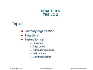
LC-3 Architecture • Very RISC, only 15 instructions • 16-bit data and address • 8 general purpose registers (GPR) • Program Counter (PC) • Instruction Register (IR) • Condition Code Register (CC) • Process Status Register (PSR) 4
Instruction Fetch / Execute Cycle In addition to input & output a program also: • Evaluates arithmetic & logical functions to determine values to assign to variable. • Determines the order of execution of the statements in the program. • In assembly this distinction is captured in the notion of arithmetic, logical, and control instructions. 5
Instruction Fetch / Execute Cycle Arithmetic and logical instructions evaluate variables and assign new values to variables. Control instructions test or compare values of a variable and makes decisions about what instruction is to be executed next. Program Counter (PC) Basically the address at which the current executing instruction exists. 6
Instruction Fetch / Execute Cycle • load rega, 10 • load regb, 20 • add regc, rega, regb • beq regc, regd, 8 • store regd, rege • store regc, regd • load regb, 15 • load rega, 30 PC Address *Note: This is just pseudo assembly code 7
Instruction Fetch / Execute Cycle The CPU begins the execution of an instruction by supplying the value of the PC to the memory & initiating a read operation (fetch). The CPU “decodes” the instruction by identifying the opcode and the operands. PC increments automatically unless a control instruction is used. 8
Instruction Fetch / Execute Cycle For example: PC ADD A, B, C • CPU fetches instruction • Decodes it and sees it is an add operation, needs to get values for the variables “B” & “C” • Gets the variable “B” from a register or memory • Does the same for variable “C” • Does the “add” operation and stores the result in location register for variable “A” 9
Instruction Fetch / Execute Cycle Branch – like a goto instruction, next instruction to be fetched & executed is an instruction other than the next in memory. ADD A, B, C BRn fred ADD A, D, 3fred ADD A, D, 4 If A is negative then next instruction to be executed is at fred, which is just an address *Note: This is almost real LC-3 assembly 10
ADD a, b, c Breaking down an instruction add a b c Source registers/immediate Opcode Destination register 11
The Stored Program Computer 1943: ENIAC • Presper Eckert and John Mauchly -- first general electronic computer. (or was it John V. Atanasoff in 1939?) • Hard-wired program -- settings of dials and switches. 1944: Beginnings of EDVAC • among other improvements, includes program stored in memory 1945: John von Neumann • wrote a report on the stored program concept, known as the First Draft of a Report on EDVAC 12
First Draft of a Report on EDVAC • The basic structure proposed in the draft became known as the “von Neumann machine” (or model). • This machine/model had five main components: • a memory, containing instructions and data • a processing unit, for performing arithmetic and logical operations • a control unit, for interpreting instructions • and input and output to get data into and out of the system. 13
Von Neumann Model* * A slightly modified version of Von Neumann’s original diagram 14
Locality of reference • We need techniques to reduce the instruction size. From observation of programs we see that a small and predictable set of variables tend to be referenced much more often than other variables. • Basically, locality is an indication that memory is not referenced randomly. • This is where the use of registers comes into play. 15
Von Neumann Model 0000 0001 0010 0011 0100 0101 0110 1101 1110 1111 00101101 • • • 10100010 Memory address 2k x m array of stored bits: • Address • unique (k-bit) identifier of location • Contents • m-bit value stored in location Basic Operations: • LOAD • read a value from a memory location • STORE • write a value to a memory location contents 16
Von Neumann Model Interface to Memory How does the processing unit get data to/from memory? MAR: Memory Address Register MDR: Memory Data Register To LOAD a location (A): • Write the address (A) into the MAR. • Send a “read” signal to the memory. • Read the data from MDR. To STORE a value (X) to a location (A): • Write the data (X) to the MDR. • Write the address (A) into the MAR. • Send a “write” signal to the memory. 17
Von Neumann Model Processing Unit Functional Units • ALU = Arithmetic and Logic Unit • could have many functional units.some of them special-purpose(multiply, square root, …) • LC-3 performs ADD, AND, NOT Registers • Small, temporary storage • Operands and results of functional units • LC-3 has eight registers (R0, …, R7), each 16 bits wide Word Size • number of bits normally processed by ALU in one instruction • also width of registers • LC-3 is 16 bits 18
Von Neumann Model Input and Output Devices for getting data into and out of computer memory Each device has its own interface,usually a set of registers like thememory’s MAR and MDR • LC-3 supports keyboard (input) and monitor (output) • keyboard: data register (KBDR) and status register (KBSR) • monitor: data register (DDR) and status register (DSR) Some devices provide both input and output • disk, network The program that controls access to a device is usually called a driver. 19
Von Neumann Model Control Unit Controls the execution of the program Instruction Register (IR) contains the current instruction. Program Counter(PC) contains the address of the next instruction to be executed. Control unit: • reads an instruction from memory • the instruction’s address is in the PC • interprets the instruction, generating signals that tell the other components what to do • an instruction may take many machine cycles to complete 20
Instructions The instruction is the fundamental unit of work. Specifies two things: • opcode: operation to be performed • operands: data/locations to be used for operation 21
Instructions An instruction is encoded as a sequence of bits. (Like data) • Often, but not always, instructions have a fixed length, such as 16 or 32 bits. • Control unit interprets instruction:generates sequence of control signals to carry out operation. • Operation is either executed completely, or not at all. A computer’s instructions and their formats is known as its Instruction Set Architecture (ISA). 22
Instructions Ex: LC-3 ADD Instruction LC-3 has 16-bit instructions. • Each instruction has a four-bit opcode, bits [15:12]. LC-3 has 8 registers (R0-R7) for temp. storage. • Sources and destination of ADD are registers. “Add the contents of R2 to the contents of R6, and store the result in R6.” 23
Instructions Ex: LC-3 LDR Instruction Load instruction -- reads data from memory Base + offset mode: • add offset to base register - result is memory address • load from memory address into destination register “Add the value 6 to the contents of R3 to form a memory address. Load the contents of that memory location to R2.” 24
Instruction Processing Fetch instruction from memory Decode instruction Evaluate address Fetch operands from memory Execute operation Store result 25
Instruction Processing F D EA OP EX S FETCH Load next instruction (at address stored in PC) from memory into Instruction Register (IR). • Copy contents of PC into MAR. • Send “read” signal to memory. • Copy contents of MDR into IR. Then increment PC, so that it points to the next instruction in sequence. • PC becomes PC+1. 26
Instruction Processing F D EA OP EX S DECODE First identify the opcode. • In LC-3, this is always the first four bits of instruction. • A 4-to-16 decoder asserts a control line corresponding to the desired opcode. Depending on opcode, identify other operands from the remaining bits. • Example: • for LDR, last six bits is offset • for ADD, last three bits is source operand #2 27
Instruction Processing F D EA OP EX S EVALUATE ADDRESS For instructions that require memory access, compute address used for access. Examples: • add offset to base register (as in LDR) • add offset to PC • add offset to zero 28
Instruction Processing F D EA OP EX S FETCH OPERANDS Obtain source operands needed to perform operation. Examples: • load data from memory (LDR) • read data from register file (ADD) 29
Instruction Processing F D EA OP EX S EXECUTE Perform the operation, using the source operands. Examples: • send operands to ALU and assert ADD signal • do nothing (e.g., for loads and stores) 30
Instruction Processing F D EA OP EX S STORE RESULT Write results to destination.(register or memory) Examples: • result of ADD is placed in destination register • result of memory load is placed in destination register • for store instruction, data is stored to memory • write address to MAR, data to MDR • assert WRITE signal to memory 31
Changing the Sequence of Instructions In the FETCH phase, we increment the Program Counter by 1. What if we don’t want to always execute the instruction that follows this one? • examples: loop, if-then, function call 32
Changing the Sequence of Instructions We need special instructions that change the contents of the PC. These are those control instructions from before. • jumps are unconditional – they always change the PC • branches are conditional – they change the PC only if some condition is true (e.g., the result of an ADD is zero) 33
Changing the Sequence of Instructions Ex: LC-3 JMP Set the PC to the value contained in a register. This becomes the address of the next instruction to fetch. “Load the contents of R3 into the PC.” 34
Instruction Processing Summary Instructions look just like data – it’s all interpretation. Three basic kinds of instructions: • computational instructions (ADD, AND, …) • data movement instructions (LD, ST, …) • control instructions (JMP, BRnz, …) 35
Instruction Processing Summary Six basic phases of instruction processing: F D EA OP EX S • Not all phases are needed by every instruction • Phases may take more than 1 machine cycle 36
Questions? 37