Download
1 / 11
110 likes | 261 Views
ECAL simulations for endcap upgrades. Laura Bergsten, Feb 2014. CMS Background. Particle detector with 4 main layers: muon detector electromagnetic calorimeter (ECAL) tracking system “ hermetic ” hadron calorimenter (HCAL). CMS public site: Lucas Taylor, 2011

E N D
ECAL simulations for endcap upgrades Laura Bergsten, Feb 2014
CMS Background • Particle detector with 4 main layers: • muon detector • electromagnetic calorimeter (ECAL) • tracking system • “hermetic” hadron calorimenter (HCAL) CMS public site: Lucas Taylor, 2011 http://cms.web.cern.ch/news/cms-detector-design
Texas Tech Experimental HEP Group • Improving the sensitivity of the CMS detector to jet physics • Upgrades for the CMS calorimeter endcaps Endcap replacement image: S. Kunori, Texas Tech University, 31-Jan-2014
My own Project Background • Understanding calorimeters • Scintillating fibers (glowing) • Cerenkov radiation (optical fibers) • Radiation damage • Fibers dimming over time • Replace calorimeters by 2020 (optimization) • 100 simulations • Analyze data, find discrepancies Photo of ECAL fibers lit from behind: S. Kunori, Texas Tech University: 31-Jan-2014
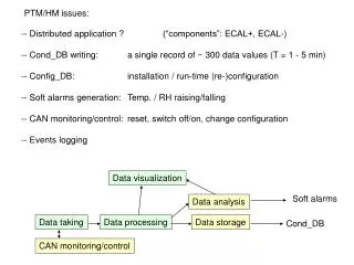
depth vs. t Depth: distance from origin to location where particle hits fiber (mm) Time: time to move particle from origin to fiber (ns)
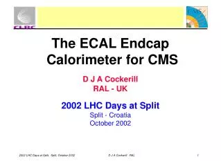
depth overlay • Comparing depth of electrons and pions • Pions penetrate deeper and strike more various locations
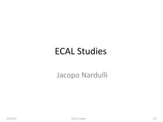
Moliere radius pions • Changed the angle of the fx vs. fy data and found x and y projections. Then sorted information to find the bin boundaries at which 95% of the data lies between (in y projection). electrons Calculated moliere radii Electron Scin: 44 mm Electron Opt: 38 mm Pion Scin: 37.5 mm Pion Opt:15 mm
Using absorption • Absorption length (index of absorption): use values from 1-10 m • μ = 1/abslength • Total distance traveled by particle (where c is speed of light, n is index of refraction) • Dtot = tprop * c/n • Probability of photon without radiation damage: • Probability function: P = e-Dtot*μ • Add probability to all calculations for more accuracy
Many new plots • Create 20 plots for each needed comparison- changing the μ value from 1- 10 m indicating the dimming of the fibers due to radiation
Testing depth (electrons) depth Test 2: fx vs. depth Test 1: 3 single fibers fx
Thanks to Dr. Alexander Ledovoskoy for all his guidance and help, to University of Michigan for this opportunity, and to the Texas Tech group for letting me join their group!