Download
1 / 30
300 likes | 527 Views
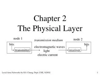
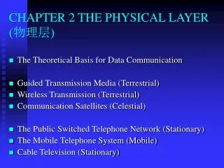
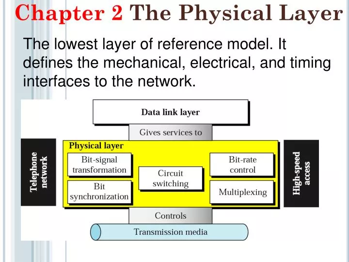
The lowest layer of reference model. It defines the mechanical, electrical, and timing interfaces to the network. Chapter 2 The Physical Layer. BANDWIDTH AND INFORMATION CAPACITY.

E N D
The lowest layer of reference model. It defines the mechanical, electrical, and timing interfaces to the network. Chapter 2 The Physical Layer
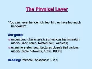
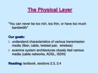
BANDWIDTH AND INFORMATION CAPACITY Bandwidthis the span of frequencies within the spectrum occupied by a signal and used by the signal for conveying information. Carrying information requires bandwidth.
Noiseless Channel: Nyquist Bit Rate L is the number of signal levels used to represent data. Increasing the levels of a signal may reduce the reliability of the system.
Noisy Channel: Shannon Capacity The theoretical highest data rate for a noisy channel where capacity is in bits/second, bandwidth is in hertz, and signal and noise powers are measured in the same physical units, such as watts. Bits are fundamental units of information.
Using both limits The Shannon capacity gives us the upper limit; the Nyquist formula tells us how many signal levels we need.
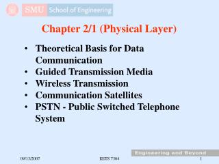
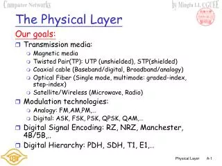
Guided Transmission Data • Magnetic Media • Twisted Pair • Coaxial Cable • Fiber Optics WirelessTransmission • The Electromagnetic Spectrum • Radio Transmission • Microwave Transmission • Infrared and Millimeter Waves • Lightwave Transmission
Twisted Pairs Category 5e UTP cable with four twisted pairs
Coaxial Cable A coaxial cable
Power Lines A network that uses household electrical wiring.
Fiber Cables (a) Side view of a single fiber. (b) End view of a sheath with three fibers.
Digital Subscriber Lines (3) A typical ADSL equipment configuration.
Fiber To The Home Passive optical network for Fiber To The Home.
Modems (a) A binary signal (b) Amplitude modulation (c) Frequency modulation (d) Phase modulation
Signal Encoding Techniques • Digital data, digital signal(Ethernet) • Analog data, digital signal(PCM) • Digital data, analog signal(ADSL) • Analog data, analog signal(phone)
Biphase • Manchester • Transition in middle of each bit period • Transition serves as clock and data • Low to high represents one • High to low represents zero • Used by IEEE 802.3 • Differential Manchester • Mid-bit transition is clocking only • Transition at start of a bit period represents zero • No transition at start of a bit period represents one • Note: this is a differential encoding scheme • Used by IEEE 802.5
TQ 6. The waveform of following figure belongs to a Manchester encoded binary data stream. Determine the beginning and end of bit periods (i.e., extract clock information) and give the data sequence.
Bipolar (+, 0, - voltages) schemes Alternate Mark Inversion (AMI): 1s are represented by alternating positive and negative voltages.
Note In mBnL schemes, a pattern of m data elements is encoded as a pattern of n signal elements in which 2m ≤ Ln.