Download
1 / 31
330 likes | 497 Views
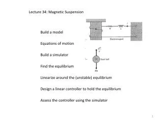
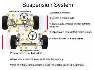
Magnetic Suspension System Control Using Position and Current Feedback. Team: Gary Boline and Andrew Michalets Advisors: Dr. Anakwa and Dr. Schertz. Applications of a Magnetic Suspension System. Electromagnetic Suspension Train. Frictionless Magnetic Bearings. Summary.

E N D
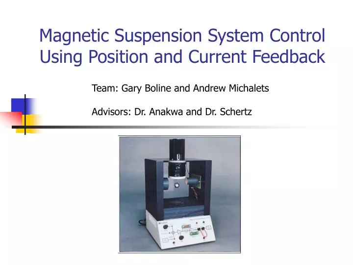
Magnetic Suspension System Control Using Position and Current Feedback Team: Gary Boline and Andrew Michalets Advisors: Dr. Anakwa and Dr. Schertz
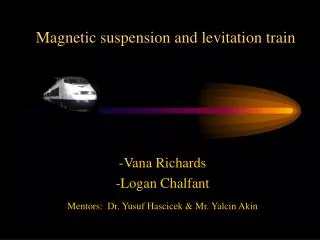
Applications of a Magnetic Suspension System Electromagnetic Suspension Train Frictionless Magnetic Bearings
Summary • Determine if Current Feedback can be utilized to improve performance • No success with Current Feedback • Develop New Position Controller • Design Methods • Implement: xPC & Coldfire
Outline • Magnetic Suspension System Overview • High Level Block Diagram • Current Modeling • Current Controller Attempts • Position Controller Development • Microcontroller Implementation • Future Suggestions • References • Questions
Outline • Magnetic Suspension System Overview • High Level Block Diagram • Current Modeling • Current Controller Attempts • Position Controller Development • Microcontroller Implementation • Future Suggestions • References • Questions
Outline • Magnetic Suspension System Overview • High Level Block Diagram • Current Modeling • Current Controller Attempts • Position Controller Development • Microcontroller Implementation • Future Suggestions • References • Questions
Current Modeling • Experimental • Simulink • Transfer Function • Rate Limiter (nonlinear)
Outline • Magnetic Suspension System Overview • High Level Block Diagram • Current Modeling • Current Controller Attempts • Position Controller Development • Microcontroller Implementation • Future Suggestions • References • Questions
Current Controller Attempts • State-space • Current with Lag, Lead, or Lag/Lead • Noise Problems • Current Feed-forward • Current Error Feed-forward • Based on Proportion to Position • Position Integrator ‘integrates’ current term out
Outline • Magnetic Suspension System Overview • High Level Block Diagram • Current Modeling • Current Controller Attempts • Position Controller Development • Microcontroller Implementation • Future Suggestions • References • Questions
Position Controller Development • Root Locus Attempts • Block Diagram • Simulation Data • Scope Plots • Performance Data vs. Specs
Position Controller Development • Root Locus • Open Loop Poles: 1.0321, 0.9689 • Closed Loop Poles: 0.9704+/-0.0077j, 0.8550, 0.3888 Expanded
Position Controller Development • Block Diagram
Position Controller Development • Step Response (simulation) • 28% OS
Position Controller Development • Step Response (xPC) • ~30% OS
Outline • Magnetic Suspension System Overview • High Level Block Diagram • Current Modeling • Current Controller Attempts • Position Controller Development • Microcontroller Implementation • Future Suggestions • References • Questions
Microcontroller Implementation • Improvements • Input/Output Configuration • System Timing • Scope Plots • Performance Data vs. Specs
D/A Converter Setup Volts (mV)Controller Output +2047 FFF : : 0 800 -1 7FF : : -2047 000
Step Response Our Controller Past Controller
Our Controller Max Amplitude : 0.2Vpp Overshoot : 47% Settling Time : 240 ms Past Controller Max Amplitude : 0.5Vpp Overshoot : 36% Settling Time : 560 ms Step Response Results Advantages: Faster System Disadvantages: Larger overshoot, Less input amplitude, Less stability
Outline • Magnetic Suspension System Overview • High Level Block Diagram • Current Modeling • Current Controller Attempts • Position Controller Development • Microcontroller Implementation • Future Suggestions • References • Questions
Future Suggestions • Lab bench space • Modularize Code • Design to realistic specs • Anti-aliasing filters • Design System Bottom Up, Current and Voltage Control Independently
References • Jose A Lopez and Winfred K. N. Anakwa, “Identification and Control of a Magnetic Suspension System using Simulink and Dspace Tools”, Proceedings of the ASEE Illinois/Indiana 2003 Sectional Conference, March 27, 2004, Peoria, Illinois, U.S.A. • Feedback Inc., 437 Dimmocks Mill Road, Hillsborough, North Carolina 27278. http://www.fbk.com • Simulink, Version 6.1 (R14SP1), The MathWorks Inc., Natick, MA 01760, 2004. • xPC Target Box, The MathWorks Inc., Natick, MA 01760, 2003.
Conclusion • Determined Current Feedback not viable • State Space • Classical • Designed New Position Controller • Root Locus • Simulation and xPC • Implemented Design on Microcontroller • Timer Driven • Faster System • Bring back focus • Step back up from lower level • Project importance at beginning • Balance additional content