Download
1 / 8
80 likes | 178 Views
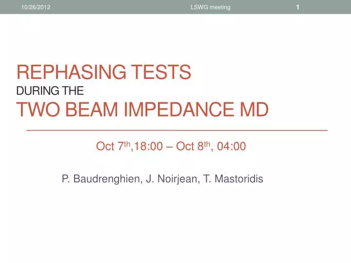
REPHASING tests during the Two Beam IMpedance MD. P. Baudrenghien, J. Noirjean, T. Mastoridis. Oct 7 th ,18:00 – Oct 8 th , 04:00. Motivation: TBI MD ( S.Fartoukh ).

E N D
LSWG meeting REPHASING tests during the Two Beam IMpedance MD P. Baudrenghien, J. Noirjean, T. Mastoridis Oct 7th,18:00 – Oct 8th, 04:00
LSWG meeting Motivation: TBI MD (S.Fartoukh) • A discrepancy by up to a factor of 3 remains to be explained for the octupole threshold current depending on whether one beam or two beams are circulating in the LHC ring • The existence of a two-beam-impedance effect is strongly conjectured. This effect would be driven by one or several 2-in-1 structures shared by the two beams, to be identified, such as the Y-chamber, the TCTV in IR8, the TDI in IR2 and IR8,… • The test consists in operating the machine with a dedicated filling scheme, and then displacing Beam2 clockwise via the RF (rephasing by multiple of ¼ turn) in order to generate machine configurations where the two beams do not see each other in any of the four experimental IR’s, or meet only in IR1/5, only in IR2, or only in IR8 • In each of these configurations, the aim is to reduce the octupole settings and/or the linear chromaticity till an instability starts to be visible on the BBQ • HOWEVER… • The MD suffered from several machine problems: adjusting the injection (18:00-23:30), then sector 12 trip (01:30-end). Only 2 hours with beam… • The little time with beam was mainly used to validate the rephasing at 450 GeV and 4 TeV, as requested by MP edms doc 1244098, Two-Beam inpedance MD, S. Fartoukh
LSWG meeting Rephasing • In order to displace the crossing azimuth (z-coordinate) of the two beams, we need to make the two revolution frequencies different • That implies a change of momentum, and a displacement of the mean orbit • We have accepted +Dp/p=1E-4, corresponding to -12 Hz @ 400 MHz and +0.1 mm mean orbit displacement
LSWG meeting Procedure Acceleration/deceleration rate df/dt is limited by adiabaticity requirement: the bucket is displaced in momentum and the bunch must follow without loss Max Df is limited by acceptable momentum offset • We accelerate (decelerate) one beam to an off-centered orbit • After a time t, the phase has drifted by • The crossing azimuth drifts by half that value (if we move one beam only) • When the desired position is reached we decelerate (accelerate) back to the centered orbit
LSWG meeting Rephasing at 450 GeV/c • 6b+6b+32b in each ring, nominal bunch intensity • We moved beam 2 by ¼ turn clockwise by changing its RF frequency by -12 Hz • The crossing point has moved 1/8th turn clockwise • With the -12 Hz frequency offset, it takes 12.5 minutes to rotate ¼ turn • No loss, no lifetime degradation, no increase in abort gap population FBCT Atlas BPTX ¼ turn Abort Gap intensity 12.5 minutes 0.11mm DR 0.1E-3 Dp/p
LSWG meeting Rephasing at 4 TeV/c • 1b in each ring, nominal bunch intensity • Same displacement of mean orbit (+0.1 mm) and Dp/p (+0.1E-3) • We observed a very short drop in lifetime at start of rephasing bump • Also drop in FBCT at start and end bump(~ 1 per mil) • This suggests that the acceleration/deceleration to the off-centered orbit is not completely adiabatic when done at 4 TeV/c FBCT ~1 per mil loss 12.5 minutes Energy
LSWG meeting 450 GeV/c vs. 4 TeV/c 4psfspemittance (86.5% of bunch intensity contour) 6psfspemittance (95% of bunch intensity contour) 4000 GeV conditions: 1.25 ns 4s length, 12 MV Bucket: 4E-4 half height dp/p, 5.2 eVs area Bunch: 2.5 eVsemittance (4psssE), fs= 26 Hz 450 GeV conditions: 1.25 ns 4s length, 6 MV Bucket: 8E-4 half height dp/p, 1.2 eVs area Bunch: 0.6 eVsemittance (4psssE), fs= 55 Hz • During the displacement to and from the off-centered orbit (1.2 seconds), we move the bucket vertically • by 1/8th bucket half height in 66 synchrotron periods at 450 GeV/c • By 1/4th bucket half height in 31 synchrotron periods at 4 TeV/c • Improvement: reduce the rate of frequency change to 1 Hz/s to be adiabatic at 4 TeV
LSWG meeting Conclusion • As requested by MP, the rephasing has been validated with high intensity beams at both 450 GeV and 4 TeV • In the future we will use 1 Hz/s rate and -12 Hz frequency offset (1E-4 Dp/p) • With these settings we move one beam by ¼ turn in 13 minutes • For large rephasing angles, the time scales linearly with the azimuthal rotation • We are ready for the next TBI MD… • For very small shifts (below 144 RF buckets), the rephasing is completed before the maximum momentum offset is reached. Rephasing time then scales as the square root of the desired displacement. For example • 2 seconds to move 1 beam by 1 RF period • 4.5 seconds to move 1 beam by 5 RF periods (2.5E-5 max Dp/p)