Download
1 / 13
130 likes | 281 Views
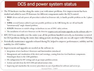
Status & Plans DCS WS 10.3.03 L.Jirdén. 2002. 03. 04. 05. 06. 07. DET. PRE-INST. FINALINST. COM-MISS. BEAMOP. DCS. URD. ENG. SOLUTIONS. PROTOTYPE SUBSYSTEM. PROTOTYPE SUB-DET CONTR. TEST WITH DETECTOR EQUIPMENT. INSTALL DCS INFRASTRUCTURE. INSTALL DETECTOR DCS. DCS Planning.

E N D
2002 03 04 05 06 07 DET PRE-INST FINALINST COM-MISS BEAMOP DCS URD ENG. SOLUTIONS PROTOTYPE SUBSYSTEM PROTOTYPE SUB-DET CONTR. TEST WITH DETECTOR EQUIPMENT INSTALL DCS INFRASTRUCTURE INSTALL DETECTOR DCS DCS Planning
1st draft URD exists Discussion started Not started PHO MU CAL CPV TRI TRA Status URD’sMarch 03 DCS … ITS TPC TRD TOF HMP ZDC FMD T0 V0 PMD EMC COS Detectors SPD SDD SSD RO FC HV HV HV HV HV HV HV HV HV HV HV HV HV HV HV HV HV HV HV LV LV LV LV LV LV LV LV LV LV LV LV LV LV LV LV LV LV subsystems FEE FEE FEE FEE FEE FEE FEE FEE FEE FEE FEE FEE FEE TMP TMP TMP TMP TMP TMP TMP TMP TMP TMP TMP TMP TMP TMP TMP TMP TMP TMP TMP COO COO COO COO COO COO COO COO COO COO COO COO COO GAS GAS GAS GAS GAS GAS GAS GAS GAS TS LSR ROD TS LIQ ALI PLS
Detector DCS Milestones • User Requirements Document (URD) mid 2002 • Lab setup end 2002 • Individual sub-system • Connection to PVSS, some panels, limited logging and configuration facilities
1st version exists started not started PHO MU CAL CPV TRI TRA Status PrototypesMarch 03 DCS … ITS TPC TRD TOF HMP ZDC FMD T0 V0 PMD EMC COS Detectors SPD SDD SSD RO FC HV HV HV HV HV HV HV HV HV HV HV HV HV HV HV HV HV HV HV LV LV LV LV LV LV LV LV LV LV LV LV LV LV LV LV LV LV subsystems FEE FEE FEE FEE FEE FEE FEE FEE FEE FEE FEE FEE FEE TMP TMP TMP TMP TMP TMP TMP TMP TMP TMP TMP TMP TMP TMP TMP TMP TMP TMP TMP COO COO COO COO COO COO COO COO COO COO COO COO COO GAS GAS GAS GAS GAS GAS GAS GAS GAS TS LSR ROD TS LIQ ALI PLS
Detector DCS Milestones • User Requirements Document (URD) mid 2002 • Lab setup end 2002 • Individual sub-system • Connection to PVSS, some panels, limited logging and configuration facilities • Intermediate detector tests & test beams mid 2003 • A few sub-systems involved • Subsystem as finite state machine • Pre-installation tests mid 2004 • All sub-systems involved • Extended logging, configuration and alarm facilities • Detector as finite state machine • ECS and liaisons with DAQ, TRG • Final installation mid 2005 • Commissioning mid 2006
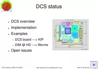
LV CONTROL Functionality (FSM) COMPUTER Logging Access handling SUPERVISORYLAYER PVSS Config. OPC client Alarm handling LV CU PVSS DCS network PROCESS LAYER COMPUTER LV DU Functionality (FSM) OPC server Alarm handling Logging PCI-CAN Config. Device driver CAN-bus FIELD LAYER PVSS CAN contr. LV Physical Device WIENER LV TPC test case
COMPUTER SUPERVISORYLAYER PVSS OPC clients DCS network PROCESS LAYER COMPUTER COMPUTER COMPUTER COMPUTER PLC OPC server OPC server DIM server OPC server PCI-CAN PCI-CAN PCI-Profib. Profibus CAN-bus CAN-bus CAN-bus FIELD LAYER CAN contr. CAN contr. Profib contr. CAN contr. WIENER LV ISEG HV FEE (RCU) COOLING DEVICES TPC test case
ECS DCS DAQ TPC LV CU HV CU FEE CU COOL CU LV DU HV DU FEE DU COOL DU LV Physical Device HV Physical Device FEE Physical Device COOLING Physical Device TPC test case
Needed today • URD’s • A 1st version from all remaining detectors • A 2nd version from all main detectors covering • All sub-systems • Operational requirements: state/transition diagrams • for sub-systems • Interlocks • Planning: milestones table for each sub-system • Budget: Central DCS and Detector DCS estimate • Prototyping • All detectors to start prototyping • Start using PVSS FW and one common solution • Make a “Lab Setup” • Central team to provide and support the necessary standard tools and components
Tools USER APPLICATION Supervisory layer Dbase FRAMEWORK: Back-end Tools and components DCS network Process layer USER APPLICATION FRAMEWORK: Front-end Tools and components Field layer Field-bus DEV 1 DEV 2
Detector resp. USER APPLICATION ACC resp. ACC resp. ALICE resp. Supervisory layer FRAMEWORK CONDIT FSM ALARM DB access ARCHIV PVSS CONFIG LOG ARCHIV DET CONFIG LOG FEE CONFIG COMMUNICATION WEB PVSS CONFIG DCS network DBMS Process layer Standard: ACC resp. Specific: Detector resp. COMMUNICATION Detector resp. USER APPLICATION Standard: ACC resp. Specific: Detector resp. DEVICE DRIVERS Field layer Field-bus Detector resp. DEV 1 DEV 2 Tools ALICE resp.
Needed mid 2003 • URD’s • Operational requirements: state/transition diagrams • for sub-detectors • Prototyping • 1 - 2 sub-systems prototyped with FSM functionality