Download
1 / 16
160 likes | 302 Views
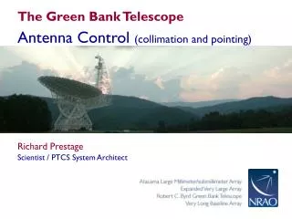
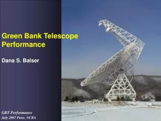
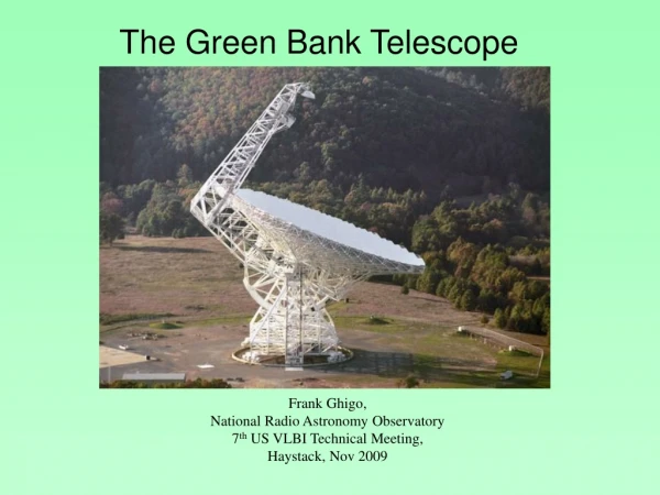
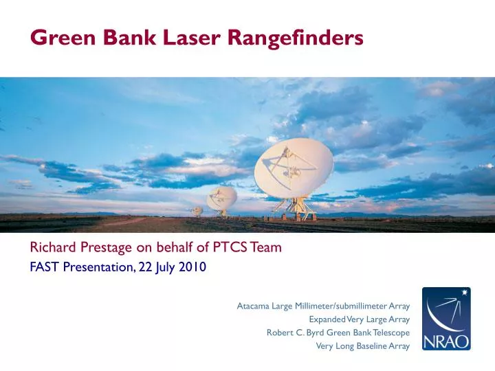
Green Bank Laser Rangefinders. Richard Prestage on behalf of PTCS Team. FAST Presentation, 22 July 2010. LRF Overview. Project conceived in early 1990s, as an integral part of GBT Development. Requirement was for ~ 100µm ranges over ~ 100m distance. No commercial technology available.

E N D
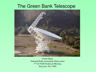
Green Bank Laser Rangefinders • Richard Prestage on behalf of PTCS Team • FAST Presentation, 22 July 2010
LRF Overview • Project conceived in early 1990s, as an integral part of GBT Development. • Requirement was for ~ 100µm ranges over ~ 100m distance. • No commercial technology available. • Made possible by the evolution of commercial off the shelf hardware and software. • E.g. availability of laser diodes with built in GRIN lenses that can be directly modulated at 1500 MHz for less than $150 as a result of consumer electronics CD players.
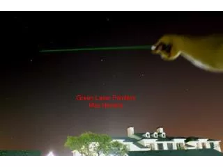
Principle of Operation • 780nm semiconductor lasers modulated at 1.5GHz • Light returned by target retroreflectors, detected and mixed with transmitted signal • Phase difference converted to distance (so distance must be known a priori to ± 50mm
Intended Operation • LRFs to provide absolute measurements of pose (pointing) and surface figure (efficiency) • Goal was to provide ~ 2” absolute pointing, and ~ 250-300µm surface accuracy • Compensate for thermal and (slowly varying) wind effects • Closed loop control of Active Surface • Requires ~ 100µm accuracy over 100m ranges (1ppm) • Requires a few (2-5)range measurements per second, with potentially large angular motions (1 radian) • Index of refraction of air varies by ~ 1ppm / °C • Must measure atmospheric conditions and adjust index of refraction
LRF Configurations • 6 LRFs onfeedarmtrilaterate to retroreflector prisms (one per panel) • Correct for wind variations in position of feedarm by trilaterating to reference retroreflectors • Correct for structural vibrations of feedarm using accelerometer data • Use corrected ranges to solve for Zernike polynomial expansion of the wavefront error • 12 LRFs mounted on ground monuments trilaterate to retroreflectors mounted on alidade and tipping structure (including “triplet” retroreflectors mounted on rim of primary) • Measure “traditional” terms in pointing model directly (e.g. elevation axis collimation angle, azimuth zero point). • Measure departure of structure from ideal performance.
Status as of mid 2003 • 20 “First Generation” LRF units constructed. • Basic performance at the ~100µm level for individual ranges demonstrated • LRF control software and basic range measurement software in place • Initial “phase closure” experiments performed • Making measurements in a 2-d horizontal plane between 12 ground monuments • ~ 200 µm accuracies in position achieved.
2003 “NCP trilateration Experiment” • Antenna pointed to a ~stationary, bright calibrator at the North Celestial Pole • Astronomical “peak” and “focus” measurements performed • Extensive environmental information (air and structural temperatures, wind speed, etc) gathered • Ranges measured to tip of feedarm • Traditional survey to same targets performed with Topcon surveying instrument. • Discrepancies of the Topcon survey and LRF-calculated target positions of the order of a few mm. • At this point, further work on use of this version of the LRF for GBT surface setting / pointing improvements was put on hold.
Concerns with LRF Performance • How to measure Group Index of Refraction • Geometry of system: “long skinny triangles”; relaying coordinate systems • System Integration Concerns • Difficulty of integrating LRF usage into GBT control software, and astronomical (incremental, differential) improvements to pointing and surface adjustments
Geometry Concern • Estimated position error ~ 1.4mm for nominal GRI and range errors
Subsequent Developments • 2005: “Second Generation” metrology system • Fixed baseline system, range and angle measurements made by instruments mounted on GBT. • Relay a fiducial coordinate created at the pintle bearing by high performance inclinometers (like “ALMA reference telescope”) • Use a two-tone system with incommensurate frequencies • DDS synthesisers • MEMS fiber optic switches • Performance improved, but still not adequate • Cross talk, phase nonlinearities
Subsequent Developments • 2008: “Third Generation” rangefinders • Addressed problems with DDS synthesiser programming, cross-coupling, phase instabilities and component nonlinearities. • Accuracy is currently limited by phse detection nonlinearities. • These are systematic and potentially correctable by providing a defined reference target. • This generation LRF should meet spec of ~ 100µm range over ~ 100m • BUT: Currently we are close to pointing and surface accuracy specifications using advanced and innovative applications of “traditional” astronomical correction techniques (e.g. with phase and phase retrieval holography; quadrant detector, etc). • Currently no plans to continue rangefinder development.