Download
1 / 31
310 likes | 410 Views
Kerstin Hoepfner for the Muon Cosmic Challenge Group With input from D. Acosta, N. Amapane, T. Christiansen, A. Colaleo, T. Cox, M. DalaValle, V. Drollinger, U. Gasparini, F. Geurts, D. Holmes, M. Maggi, N. Neumeister, T. Rodrigo CPT Week November 2005 CC meeting 04.11.2005.

E N D
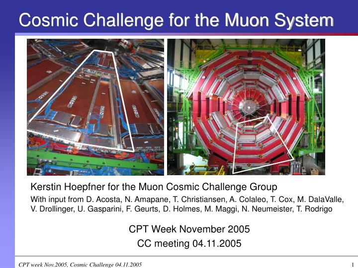
Kerstin Hoepfner for the Muon Cosmic Challenge Group With input from D. Acosta, N. Amapane, T. Christiansen, A. Colaleo, T. Cox, M. DalaValle, V. Drollinger, U. Gasparini, F. Geurts, D. Holmes, M. Maggi, N. Neumeister, T. Rodrigo CPT Week November 2005 CC meeting 04.11.2005 Cosmic Challenge for the Muon System CPT week Nov.2005, Cosmic Challenge 04.11.2005
Goals for CC in the Muon System • Detector subsystems: • Establish and finalize procedures and software • Demonstrate performance in magnetic field • Provide a live test bench for hardware (Together with B904 electronics lab) • Check system performance (resolutions, etc.) • Test full DT trigger chain • Compare data with/without B-field for drift-tube chambers • Integration with other CMS systems • Integrate the 3 muon detection subsystems • E.g., Global DAQ, Local Trigger Control • Record and reconstruct muon tracks in all 3 detector subsystems, Tracking and momentum determination • Test alignment system CPT week Nov.2005, Cosmic Challenge 04.11.2005
Endcap CSC (EMU)Readout and Trigger ElectronicsDAQ and DCSSoftware
ME4 ME3 ME2 ME1 ME4 ME4 ME3 ME3 ME2 ME2 ME1 ME1 DT DT - - 11 11 DT DT - - 10 10 A Slice of EMu – Endcap Configuration • One 60° Trigger Sector on the positive Endcap: • Sector 5, overlap with DT sectors 10-11 • Multiple stations on multiple disks • YE+1, YE+2 (and YE+3) • ME+1, ME+2, ME+3 (and ME+4) • Total of up to 36(39) chambers Provided availability of final electronics • Channels:36 stations ~1000 channels per chamber (anode wires + strip readout) = 36 000 CSC channels • DAQ options: • Local DAQ (DDU-spy channel): DQM and calibration • Global DAQ (DCC S-Link): CMS-DQM, EvF, off-line analyses Webpage – http://cern.ch/EmuSliceTest F. Geurts CPT week Nov.2005, Cosmic Challenge 04.11.2005
CSC Rates for CC Possible collected data for CSC system during CC: • Geometry: 60 degree slice of positive endcap • Trigger rate: ~150 Hz Based on measured 50 Hz measured rate for 20 degree slice for coincidence of 2 disks. Depends on how loose/tight roads are defined. Could easily grow to ~500 kHz with very loose trigger, but could be tightened to very small numbers if muon is required to go through IP. • Raw event size: ~10 kB Depends on number of chambers read out, and number of time samples. Estimate good to +-50% Data rate is roughly ~1.5 MB/sec. 24 hours ~13M cosmics, 130 GB. • Big uncertainty is how long we will run in data-taking mode, but should be prepared for O(TB) of data. D. Acosta CPT week Nov.2005, Cosmic Challenge 04.11.2005
Currently - Slice Test • 9 ME2 + 9 ME3 chambers available. Readout limited by availability of electronics 9 ME3 + 3 ME2 • Currently has 2 peripheral crates, 9 + 3 chambers hooked up, HV, gas • Data being taken @ 50Hz rate with coincidence of 2ME • Data used for verification of HW+SW (local and global DAQ, DQM, feedback for integration) • Next steps: (1) 9 + 9 chambers (2) ME3+2+1 TrackFinder Crate CPT week Nov.2005, Cosmic Challenge 04.11.2005
DT-TF interface: • Takes ME1/3 stubs from CSC • Passes MB2/1 stubs to SPs DT TF Track-Finder Crate x1 Peripheral Crate x60 GMT CSC Readout and Trigger System in CMS • CSC Chamber • 6 layers of anode wires & cathode strips • wires run parallel to , give measurement, strips perpendicular CSC Chamber x540 3 best track segments (ME2,3,4) per 60o sector In CC: G(M)T replaced by LTC • Track-Finder (TF) Crate: • 12 Sector Processors (SP). • Each SP takes hits from a 60o slice through an end-cap. • Takes MB2/1 stubs from DT & sends ME1/3 stubs to DT. • Makes tracks. • 4 best tracks from the Track Finder Crate are sent to GMT. • Peripheral Crate: • 9 Trigger mother boards (TMB), 9 DAQ mother boards (DMB). 1 pair for each chamber. • 1 Muon Port Card (MPC) passes it’s 3 favorite track segments to Track-Finder (TF). D. Holmes CPT week Nov.2005, Cosmic Challenge 04.11.2005
Trigger Back from TTC cosmic challenge; other detector subsys L1A counting house SX5 D.Holmes CPT week Nov.2005, Cosmic Challenge 04.11.2005
CSC Trigger & DCS • Sector processor (SP) triggering is very configurable • ‘CMS’ style coincident triggering; • need at least one track segment on a link corresponding to ME 2 or 3 and one in any other station. BX spread +/- 1. • need to fit within eta/phi/quality cuts • Eta cuts opened up (to relax IP constraint) • Any quality (strip hits alone are sufficient) • Can also just trigger on any LCT on any choice of links • Very useful for initial peripheral crate setup • DCS • Accessed (now) at time of peripheral crate configuration in single process • New crate controller (& code) will allow access from different processes but also provide blocking mechanism • Expect to move to new controller imminently D.Holmes CPT week Nov.2005, Cosmic Challenge 04.11.2005
Global/Local DAQ • Global DAQ tests (1st week of October) • Continuation of DCC/S-Link/FRL tests in April • EMu provides self-triggered cosmics data (3 CSCs on ME+3) over S-Link to Front-End Receiver Link (FRL) • … while running Trigger Mother Boards (TMB) validation tests on the other station • Global DAQ has set up a dedicated ReadoutUnit (RU) / BuilderUnit (BU) / FilterUnit (FU) DAQ column • It works! • However, very low rate at the FilterUnit (100kb/s), and .. • DAQ column not (yet) robust against gaps in or resets of event numbers • Progress in DDU monitoring tools: • Dmonitor watches over DDU via VME • Previously only through DDU header/trailer • Now that SliceTest set-up is (almost) available again: start assuming “24/7” operation, monitoring for rare problems. D.Holmes CPT week Nov.2005, Cosmic Challenge 04.11.2005
Barrel Drift Tubes Readout and Trigger ElectronicsDAQ and DCSSoftware
4 1 7 11 10 Barrel Detector Configuration for CC Instrumented sectors (DT+RPC) used in the cosmic challenge: YB+2 sectors 10, 11 YB+1 sector 10 3 sectors, 14 chambers (sector 10 has 5 chambers since MB4 is splitted in two) The 3 sectors must will be made "fully operational", cabling of these sectors has to be completed (delayed!), HV and LV incl. supplies, cables and racks (on their way). Webpage – http://cmsdoc.cern.ch/cms/MUON/dt/CC/cc.html CPT week Nov.2005, Cosmic Challenge 04.11.2005
DT Rates • Commissioning data taking rate ~0.5 kHz(depending on sector). Measured rates for sec.10 are ~620 Hz (MB1) and ~530 Hz (MB3). Sec.11 ~20% less due to inclination. • Cosmic challenge with 3 sectors ~1.5 kHz rate • DAQ rate-to-tape depends on event size (= which subdetectors are included). Working assumption <50 MB/s "rate-to-tape" (T.Christiansen) max. trigger rate O(100 Hz) if all subsystems, without data reduction O(1000 Hz) for muon only • Measured data size 0.2 kB/chamber ~1 kB/sector • Plans for data taking: • Take max. amount of muon data (that is without tracker) ~1.5 kHz provide L1A and read all cosmics with full rate • Narrowing the angular acceptance of the trigger to match with tracker, strong reduction in acceptance take maximum "rate-to-tape" of ~100 Hz, of which 1-4% are muons crossing all subsystems CPT week Nov.2005, Cosmic Challenge 04.11.2005
Detector in UXC DT front end Barrel Trigger Boards (BTI,TRACO,TSS) C C B DT station (minicrate) LVDS copper link Towers in UXC Server Board Sector Collector Opto link DT Sorter DT Track Finder Counting room in USC GLOBAL MUON TRIGGER DT Barrel Trigger Electronics • Goal: Test the FULL system • Local trigger with B-field • Trigger boards on-chamber in mini-crate. Tested in testbeam 2004 without B-field. Two best muon segments on output from each chamber. • Regional trigger • Accepts DT segments from all 4 stations in a sector + neighbours (also CSC segments in “overlap” region). Combines segments into full tracks and assigns Pt, , , quality to each muon track. • Global trigger • A sector collector (SC) board serves a sector (4/5 stations). Track sorting (1 out of 2 tcks/station) and DT trigger path syncronization (compensation of TOF, TTC fibers and LVDS cables) via clock delay and pipe lines. • If possible (rate?) also test interface with CSC (overlap region) • Provide a barrel cosmic muon trigger for CMS, baseline: regional trigger loop M. Dalavalle CPT week Nov.2005, Cosmic Challenge 04.11.2005
DT Local Trigger Loop (1) • Limited to a Sector • Sector Collector generates a local-LV1A after receiving the trigger data from chambers in the same sector. • Local-LV1A is returned to sector MiniCrates and to the sector ROS • Sector Collector decision based on simple programmable AND/OR of chamber “autotrigger” bits • MiniCrate control-configure-monitor via MC Control Board accessible through slow control • Chamber-to-chamber synchronization at the Sector Collector • Partial Trigger data also in DAQ stream (from SectColl to its pairing ROS) for monitoring and for synch of R/O and trigger M. Dalavalle CPT week Nov.2005, Cosmic Challenge 04.11.2005
Regional Trigger Loop - Baseline • Trigger Data from Sector Collectors in CMS towers via optical links to Track Finder Processors in counting room • synchronization of sectors at the TFPs • sector trigger data exchanged btwn TFPs • 3 SectColl and 3 TFP in Cosmics Challenge • Trigger logics can also correlate chambers btwn nearby sectors • TFP extrapolations are reprogrammable • TFP trigger output for LTC being designed (J.Ero) • LV1A returned to the Minicrates and the Sector Collector crate through TTC system • Spy system for monitoring the trigger data in the TFPs. • DAQ output in preparation M. Dalavalle CPT week Nov.2005, Cosmic Challenge 04.11.2005
LVDS LVDS LVDS 2 per minicrate LVDS Three main data backbones: Trigger, TDC data, Control DT DAQ & DCS Layout S. Ventura CPT week Nov.2005, Cosmic Challenge 04.11.2005
DT DAQ & DCS Schedule DCS/Trigger Backbone ready for deployment (Sector Test), with basic FM control and legacy or prototype GUI (enough for CC as well) DAQ • After hardware delivery: • - update of the ReadoutUnit software -> 2-3 weeks • daq column validation through cosmic runs -> 2-3 weeks • together with analysis tools upgrade • Ready for FED integration by mid jan 06 • FrontEndDriver (FED) – FrontendReceiverLink (FRL) validation Database (DB) Transition to Oracle has started with equipment DB (incomplete in the legacy DB ), the switch might be completed before the CC DAQ & DCS will be working S. Ventura CPT week Nov.2005, Cosmic Challenge 04.11.2005
Muon Software • Software Goals for CC: • Port/develop basic PRS-muon software functionality currently • in ORCA in the new software FrameWork (CMSSW) • - Make it running on real data in cosmic challenge environment, dealing with real detector config.maps/calib data/alignment data • - Use it for DQM, basic object reco and monitoring, and for detector analysis U. Gasparini CPT week Nov.2005, Cosmic Challenge 04.11.2005
Muon Software Building Blocks • Basic Muon Infrastructure in new FW • a) porting rec. geometry-model in new FW • b) basics objects (“digi”,”rechits” structure) • c) DDU formats decoding (raw to digi): DT/RPC • - also: retrieve L1 trigger data passed to DAQ • (eg. DTTrackFinder data) for monitoring (NEW) • d) interfaces with Databases (hardw to sw maps, • calibration (to,…), alignment (from COCOA) • -> POOL-ORA APIs, ect… • 2)Reconstruction • a) Local Muon Reconstruction • - RecHits/Segments in DT; Rechits in RPC • - retrieval of calib constants • b) Standalone Muon Reco • - track building with MuonDets only • - retrieval of alignment constants • - needs GEANE propagator replacement • d) Global Muon Reco : connect to tracker • - needs GEANE Will be available U. Gasparini, N. Amapane, T. Cox CPT week Nov.2005, Cosmic Challenge 04.11.2005
RPCs in the Cosmic Challenge Chambers and electronics: • Barrel RPC chambers are ready (YB+2 sec.10 fully cabled, sec.11 ongoing) • Installation of forward RPC chambers started Nov. 3rd • Off-chamber trigger/readout electronics is in preparation and needs to be tested in Bat.904 before any use in CC. (More news in RPC-trigger joined meeting Nov. 8th) • A technical trigger solution is in hand to provide trigger to the entire detector. DCS:will be there. DAQ and DQM depending on the readout hardware (see above, to be tested). SW is in good progress. DB access: • During the configuration of DAQ (if available) configuration DB needs to be accessed (under construction with good progress). • Data analysis will correlate RPC performance vs. environment (T, P and HV etc..) and needs to access condition DB (started on as soon needed, should be straightforward). • No calibration needed. M. Maggi CPT week Nov.2005, Cosmic Challenge 04.11.2005
RPC Barrel Sector Commissioning Purpose:check functionalities of all components of the RPC Trigger system • Preliminary sector test started on YB+1 to check RPC integrity and chamber behavior. 2 Sectors are tested in one week to check good HV/LV and Front-End Board behavior. The stability check still to come (2 weeks per sector). • Start sector commissioning with final components: trigger electronics, HV/LV, DCS, cables and software – to come Arrival of electronics boards is the limiting factor Needed hardware: • 1 Link Board Crate + Backplane + Frontplane • 15 Link Boards + 2 Control Boards + Optical package • TTC minicrate • PC with FEC-PCI card Technical Trigger dedicated to Cosmics: • One 96-strips OR signal from LB Crate • One RPC Balcony Collector for 2 sectors 6/wheel LB/CB Prototype ready October RBC design ready Ready Beginning December A.Colaleo CPT week Nov.2005, Cosmic Challenge 04.11.2005
LBBox LBBox LBBox LBBox LBBox LBBox RBC RBC RBC RBC RBC RBC LBBox LBBox LBBox LBBox LBBox LBBox 1 RBC/ 2 sectors Fiber Barrel Wheel RBC (RPC Balcony Collector) 6 Fibers/wheel RPC Balcony Collector (RBC) Part of the technical trigger, used for sector test and cosmic challenge. Can run in auto-trigger mode and provide trigger to the other system. • Receive ORs from LB (LVDS)(1 OR/double gap) • Produce Sector Trigger • Mask noisy/dead ORs • Re-Transmit input OR electrically (LVDS) to TDC • Transmit input OR optically to Counting Room (GOL) RBC (needed for sector test, part of CC trigger) Optical cables TTU (in control room) LTC (official CMS CC trigger) L1A F. Loddo CPT week Nov.2005, Cosmic Challenge 04.11.2005
CMS Alignment System 6 alignment plans in barrel ~ 1/3 of the full system will be installed for the Magnet test Link line Endcap transfer line CPT week Nov.2005, Cosmic Challenge 04.11.2005
Barrel Link Axial Transferline Alignment Configuration for Magnet Test This MAB config. Is repeated In each wheel (6 times) Alignment Layout : 1 AR + 1 LR on positive side 10 MABs (3 active lines) 6x4 transfer plates (3 per disc) ME+2, ME+3 straight line monitors (SLM) lines Muon Chambers: Barrel Sectors 10 & 11 (wheels +2,+1) Corresponding CSCs chambers Tracker Modules (2 in Disk-9) • Aim: • System commissioning (Hard & Control) • Check detector assembly tolerances & • Field effects vs system dynamic range • Monitor iron deformation (endcap disks) • Extract initial CMS geometry from B = 0 T (Optical & Cosmics) • Compare cosmic data vs optical alignment (@ B: 0 and max field) T.Rodrigo CPT week Nov.2005, Cosmic Challenge 04.11.2005
Hardware readout DAC logical structure ( see examples ) PVSS Control To be done: Oracle interface DB tables definition Framework Integration Data taking: DAQ and control is via DCS, implementation in PVSS finalized. During magnet test run in continous mode. Important: sufficient statistics for B=0. Take dedicated runs when B=on. Readout, Control & DAQ T.Rodrigo CPT week Nov.2005, Cosmic Challenge 04.11.2005
Barrel DAC: PVSS Control System • Standard Run Monitoring • Displays: • Parameters and progress of • running measurement • System status • Standard Run Control • Init • Start Single Run • Start Continuous Run • Pause • Stop • Debug • Based on the structure of system • Action • Take Image • Get centroid • Display data • Show calibration data • Show optical connections Correct sequencing and optimisation of the meas. A prototype of this software has been running stable for several weeks T.Rodrigo CPT week Nov.2005, Cosmic Challenge 04.11.2005
Optical & analog sensor rawdata DT/CSC data Geometry Database “Alignment object” contains offsets …Δxi Δyi Δzi Δαi Δβi Δγi... COCOA IN COCOA main: alignment fits COCOA OUT Offline reco (ORCA, …) underlying database (POOL-ORA) Optical & analog sensor calibration data Magnet-off Photogrammetry & Survey data MUON TRACKS COCOA Reconstruction and DB structure T.Rodrigo CPT week Nov.2005, Cosmic Challenge 04.11.2005
Summary • Muon system will participate in cosmic challenge with a large program. • Subsystems are working very hard to get ready. • First global test of alignment system. Alignment one of the main users of the magnet test. • Main goal for muon detectors is the integration of the 3 detection subsystems, data taking and track reconstruction for all of them. • Also check chamber performance and integrate in general CMS. • Data taking with/without B-field. First time all together, needs overall coordination! CPT week Nov.2005, Cosmic Challenge 04.11.2005