Download
1 / 44
440 likes | 448 Views
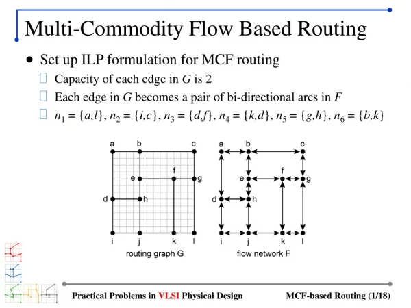
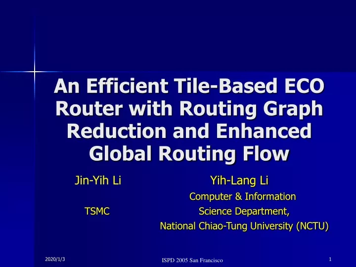
An Efficient Tile-Based ECO Router with Routing Graph Reduction and Enhanced Global Routing Flow. Jin-Yih Li Yih-Lang Li Computer & Information TSMC Science Department,

E N D
An Efficient Tile-Based ECO Router with Routing Graph Reduction and Enhanced Global Routing Flow Jin-Yih LiYih-Lang Li Computer & Information TSMC Science Department, National Chiao-Tung University (NCTU)
Outline Introduction Introduction New ECO Routing Design Flow Experimental Results Conclusion
ECO Routing • ECO routing is commonly requested toward the end of the design process to optimize delay and noise or to complete an imperfect layout. • ECO routing is highly complicated • many existing interconnections • different design rules for delay and noise issues • Most of ECO routing can be solved by p2p routing.
Routing Flow Corner-Stitching Tile Plane Construction Tile Propagation Path Construction TheDesign Flow of Tile-Based Router 8 tiles
Tile Propagation C10 T C11 C9 C7 C8 C6 C5 C4 C3 S C1 C2
Path Construction • Path Construction • generates a minimum-corner path that passes through the list of visited tiles. * *
Routing Example • Contour Insertion
Routing Example • Corner Stitching Tile Plane Creation
Routing Example • Tile Propagation
Routing Example • Path construction
Challenges for Tile-based ECO Routing • Tile fragmentation – too many slim tiles • Reducing the no. of tiles can promote router speed A horizontal-layer tile plane without contour insertion A horizontal-layer tile plane after contour insertion
Contributions of This Work • We propose routing graph reduction to reduce tile fragmentation so that the ECO router can run twice as fast without sacrificing routing quality. • We propose a newly enhanced global routing flow to reduce the runtime of ECO routing by around 89%
Introduction New ECO Routing Design Flow Experimental Results Conclusions New ECO Routing Design Flow
New ECO Routing Design Flow Build corner-stitching tile planes Redundant Tiles Removal Routing Graph Reduction Neighboring Tiles Alignment GCell Restructuring Global Routing Fail No Feasible Solution ExtendedRouting Tile Propagation Success Feasible Solution Found Enhanced Global Routing Flow Path Construction
Redundant Tiles Removal • Definitionconjunct tile. A tile A is referred to a conjunct tile of a tile B if the tile propagation from A to B on the same layer or across adjacent layer is feasible. • Definition1-conjunct. A space tile is said to be one-conjunct if it has only one conjunct tile. • Definition0-conjunct. A space tile is said to be 0-conjunct if it has no conjunct tile.
Redundant Tiles Removal • The 1-conjunct space tile is redundant because those paths that enter a 1-conjunct space tile have no exit. • The 0-conjunct space tile is redundant because it can not be reached from any other space tile. • We remove these redundant tiles within an enumeration over the whole tile plane.
Redundant Tiles Removal T1(1-conjunct) T2(0-conjunct) T3(1-conjunct) ( the region that can accommodate new via) Block Tile Space Tile Via region Block Tile : 10 Space Tile: 16
Redundant Tiles Removal Block Tile : 10 6 Space Tile: 16 13 26 19
Neighboring Tiles Alignment • We can adjust and align the left and right sides of two adjacent block tiles to merge them as a block tile. • Adjusting border is to enlarge block tiles and to shrink space tiles. Cut lines
Neighboring Tiles Alignment T1 (T1,T2) T5 T3 (T3,T4) T2 T4 T6 (T5,T6)
Four Shrinking Cases All these four cases are trying to merge block tiles T2 and T3 Ta active tile (the tile under process) (2) (1) T1 T2 T2 T1 Ta Ta T3 T3 (3) (4) Ta Ta T2 T2 T3 T1 T3 T1
Shrinking rule: There exists no via region overlapping with the shrinking region. The shrunk tile has no top or bottom neighboring space tile whose left border is larger than or equal to the stop position and less than the start position. Shrinking Rule • Case 1 T2 T1 T1 Ta Ta Stop position Start position Stop position Start position (a) illegal (b) illegal
Shrinking Example Shrunk tile T2 Ta Block Tile : 5 Space Tile: 11
Shrinking Example T2 10 Block Tile : 5 Space Tile: 11 Total 16
Enhanced Global Routing Flow Build corner-stitching tile planes Redundant Tiles Removal Routing Graph Reduction Neighbor Tiles Alignment GCell Restructuring Global Routing Fail No Feasible Solution ExtendedRouting Tile Propagation Success Feasible Solution Found Enhanced Global Routing Flow Path Construction
Internal Edge of A GCell A B nw en nw en ew ew ns ns ws ws se se C D nw en nw en ew ew ns ns ws ws se se
t: threshold value for a routable area k: amplification scalar It’s hard to pass through a Gcell when VC < 0.01 1/VC if VC> t c = k/VC if VC≦ t Cost Function • For each vertex v in G, we define a cost c • VC = VA/A • VC: Via capacity of a GCell • VA: The total via region of a GCell • A : The area of a GCell • For each edge e in G, we define a length cost lc = 2/t.
Find Minimum-Cost Path GCell on minimum cost path : Active GCell Other: idle GCell
IPH Idle Path Heap T1 P1 T3 P1 T2 P2 GCell B (active) GCell A (idle)
Blocked GCell E A B C D
Extended Routing Pop up cells D and E’s idle path heaps and continue tile propagation E A B C D
E A B C D GCell Restructuring • GCell restructuring is performed if extended routing fails. E nw en A C B ew ns ws se D C & E’s idle path heaps are empty, so we disconnect internal edges nw and ew
GCell Rescheduling D F G
H I GCell Rescheduling D F G
Introduction New ECO Routing Design Flow Experimental Results Conclusions Experimental Results
Experimental Results Table 1. Statistics of the design under test Table 2. The number of tiles on the corner stitching tile planes Table 3. The pre-process time before routing ※ RGR: Routing Graph Reduction
½ Experimental Results Table 4. Routing results with applying Routing Graph Reduction ※T1 : (Ta-Tb)/Ta,T2 : (Ta-(Tb+Trgr))/Ta ※RT : routing time(second), WL: wire length(um)
Experimental Results Table 5. Routing results with applying Enhanced Global Routing ※ T3 : (Ta-Tc)/Ta, W : (Wc-Wa)/Wa, V: (Vc-Va)/Va ※ ER : Extended Routing, GCRS: GCell restructuring and rescheduling
Introduction New ECO Routing Design Flow Experimental Results Conclusions Conclusions
Conclusions • We propose a new ECO routing design flow to promote router speed. • routing graph reduction can reduce tile fragmentation so that tile propagation speed can be doubled. • With the enhanced global routing flow, ECO router can perform much faster at the cost of a small decline in routing quality.
THANK YOU VERY MUCH