Download
1 / 25
250 likes | 426 Views
ODR - a non-invasive Beam Size Measurement Technique for CLIC. L. Bobb 1, 2 , T. Aumeyr 1 , M. Billing 3 , E. Bravin 2 , N. Chritin 2 , P. Karataev 1 , T. Lefevre 2 , S. Mazzoni 2 John Adams Institute at Royal Holloway, Egham , Surrey, United Kingdom

E N D
ODR - a non-invasive Beam Size Measurement Technique for CLIC L. Bobb1, 2, T. Aumeyr1, M. Billing3, E. Bravin2, N. Chritin2, P. Karataev1, T. Lefevre2, S. Mazzoni2 John Adams Institute at Royal Holloway, Egham, Surrey, United Kingdom CERN European Organisation for Nuclear Research, CERN, Geneva, Switzerland Cornell University, Ithaca, New York, USA L. Bobb, BI Day, December6, 2012, Centre de Convention d'Archamps
Motivation • Aim • Diffraction Radiation • Experimental preparation for Phase 1 • Simulations • Vacuum assembly • Optical system • Future work • Outlook for Phase 2 Contents L. Bobb, BI Day, December6, 2012, Centre de Convention d'Archamps
E. Chiadroni, M. Castellano, A. Cianchi, K. Honkavaara, G. Kube, V. Merlo and F. Stella, “Non-intercepting Electron Beam Transverse Diagnostics with Optical Diffraction Radiation at the DESY FLASH Facility”, Proc. of PAC07, Albuquerque, New Mexico, USA, FRPMN027. • A.H. Lumpkin, W. J. Berg, N. S. Sereno, D. W. Rule and C. –Y. Yao, “Near-field imaging of optical diffraction radiation generated by a 7-GeV electron beam”,Phys. Rev. ST Accel. Beams 10, 022802 (2007). Most recent experiments using Optical Diffraction Radiation (ODR) for beam diagnostics • P. Karataev, S. Araki, R. Hamatsu, H. Hayano, T. Muto, G. Naumenko, A. Potylitsyn, N. Terunuma, J. Urakawa, “Beam-size measurement with Optical Diffraction Radiation at KEK Accelerator Test Facility”, Phys. Rev. Lett. 93, 244802 (2004). σy = 14 µm measured ATF2@KEK L. Bobb, BI Day, December6, 2012, Centre de Convention d'Archamps
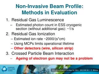
Motivation Baseline high resolution non-interceptive beam profile monitor: Laser Wire Scanners S. T. Boogert et al., “Micron-scale laser-wire scanner for the KEK Accelerator Test Facility extraction line”, Phys. Rev. S. T. – Accel. and Beams 13, 122801 (2010) Transverse beam size requirements for the Compact Linear Collider (Table 5.62 CDR Volume 1, 2012): L. Bobb, BI Day, December6, 2012, Centre de Convention d'Archamps http://www.clic-study.org/
Our experiment Project aim: To design and test an instrument to measure on the micron-scale the transverse (vertical) beam size for the Compact Linear Collider (CLIC) using incoherent Diffraction Radiation (DR) at UV/soft X-ray wavelengths. Cornell Electron Storage Ring Test Accelerator (CesrTA) beam parameters: D. Rubin et al., “CesrTA Layout and Optics”, Proc. of PAC2009, Vancouver, Canada, WE6PFP103, p. 2751. http://www.cs.cornell.edu L. Bobb, BI Day, December6, 2012, Centre de Convention d'Archamps
Principle: • Electron bunch moves through a high precision co-planar slit in a conducting screen (Si + Al coating). • Electric field of the electron bunch polarizes atoms of the screen surface. • DR is emitted in two directions: • along the particle trajectory “Forward Diffraction Radiation” (FDR) • In the direction of specular reflection “Backward Diffraction Radiation” (BDR) Diffraction Radiation θy DR Angular distribution e- θ0 Impact parameter: h Generally: DR intensity ⇧asslit size ⇩ L. Bobb, BI Day, December6, 2012, Centre de Convention d'Archamps
Vertical Beam Size Measurement using the Optical Diffraction Radiation (ODR) model + Projected Vertical Polarisation Component (PVPC) P. Karataev et al. Vertical polarisation component of 3-dimensional (θx, θy, Intensity) DR angular distribution. Visibility (Imin/Imax) of the PVPC is sensitive to vertical beam size σy. PVPC is obtained by integrating over θx to collect more photons. L. Bobb, BI Day, December6, 2012, Centre de Convention d'Archamps
Phase 1 Experiment Simulations for CesrTA Measureable visibility for initial test at parameters: λ = 200 - 400 nm a = 0.5, 1 mm σy = 50 µm To compare with TR intensities: TRmax L. Bobb, BI Day, December6, 2012, Centre de Convention d'Archamps
Beam lifetime and beam jitter M. Billing, "Introduction to Beam Diagnostics and Instrumentation for Circular Accelerators", AIP Conference Proc. 281, AIP 1993, pg.75 ff. atarget≥ 5∙σy, preferably atarget = 7-10∙σy Large aperture = low DR intensity Multiple turns of a single bunch through the target aperture Errors due to beam jitter are reduced by including turn-by-turn vertical position measurements of the bunch in the target aperture. L. Bobb, BI Day, December6, 2012, Centre de Convention d'Archamps
Target design Requirements: High precision slit size Coplanarity ≤ 10% ∙ λ High reflectivity at λ Aperture sizes a: 0.5 mm, 1 mm Material: Si L. Bobb, BI Day, December6, 2012, Centre de Convention d'Archamps Technical drawings by N. Chritin
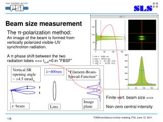
Synchrotron Radiation (SR) E = 2.1 GeV λ = 400 nm a = 0.5 mm θy e- θ0 SR + DR interference Use a mask upstream of target to suppress SR contribution. OTR ODR SR suppression P. Karataev et al., Proc. of EPAC 2004, THPLT067 L. Bobb, BI Day, December6, 2012, Centre de Convention d'Archamps Mask Target
L3 layout @CesrTA Electron beam direction DR experiment L. Bobb, BI Day, December6, 2012, Centre de Convention d'Archamps Technical drawings by N. Chritin
Vacuum chamber assembly Technical drawings by N. Chritin Simulations by A. Nosych E-field magnitude of a single bunch pass in time domain (Gaussian bunch, length = [-4s,4s], s = 10mm) H-field surface tang complex magnitude (Loss map) Mode Fr = 1.19 GHz, Q = 3309, Ploss = 0.075 W L. Bobb, BI Day, December6, 2012, Centre de Convention d'Archamps Total power loss for single bunch = 0.6 W
Vacuum chamber assembly cont’d Images taken during assembly at CERN and current testing at Cornell. L. Bobb, BI Day, December6, 2012, Centre de Convention d'Archamps
Method of Operation • Alignment of the electron beam with the target aperture: • BPMs for centering (~10 microns resolution) • Target imaging to look for OTR from beam halo • Correlate with BLMs: • DR vertical beam size measurement Quadrupole Si 1 Virtual Detector 3 Dipole 2 center -400μm off +400μm off 3 Virtual Detector 4 Virtual BLMs 4 L. Bobb, BI Day, December6, 2012, Centre de Convention d'Archamps Simulations by A. Apyan
Optical System Far-field Condition: • L = distance from source of DR to detector. • Compact optical system is in the prewave zone • (Pre-wave zone effect in transition and diffraction radiation: Problems and Solutions -P. V. Karataev). given γ and λ: L. Bobb, BI Day, December6, 2012, Centre de Convention d'Archamps
Phase 2: Micron-scale resolution • DR at soft X-ray wavelengths: • More complex optical system. • Grazing target tilt angle • Aperture size determined by impact parameter for given wavelength E = 5.3 GeV atarget= 0.2 mm Main requirement: Micron-scale resolution Must use shorter wavelengths Sensitivity @50 nm ≈ 2x sensitivity @200 nm L. Bobb, BI Day, December6, 2012, Centre de Convention d'Archamps
Summary + Conclusion • Simulations have demonstrated the feasibility of vertical beam size measurements at CesrTA. The preliminary phase 1 experiment will take place at the end of December 2012. • The design must account for the experiment location in a circular machine. This introduces some advantages and disadvantages not applicable for linacs. • Preliminary simulations for the phase 2 test aiming for the soft x-ray spectral range have been presented. Acknowledgements I would like to thank J. Barley, J. Conway, J. Lanzoni, Y. Li, T. O'Connell, M. Palmer, D. Rice, D. Rubin, J. Sexton, C. Strohman and S. Wang (@Cornell) for all technical contributions and advice. In addition, O.R. Jones and H. Schmickler for organisation of the collaboration, A. Apyan, S. Burger, A. Jeff, A. Nosych and S. Vulliez (@CERN). L. Bobb, BI Day, December6, 2012, Centre de Convention d'Archamps
Thank you for your attention Questions? L. Bobb, BI Day, December6, 2012, Centre de Convention d'Archamps
Extra slides L. Bobb, BI Day, December6, 2012, Centre de Convention d'Archamps
Higher Order Modes (HOMs) Fork OUT, Chamber IN E-field + B-field magnitude of a single bunch pass in time domain (Gaussian bunch, length = [-4s,4s], s = 10mm) H-field surface tang complex magnitude (Loss map) 1.017 GHz 1.26 GHz 1.19 GHz 1.017 GHz Ploss_total = 0.6W 1.19 GHz Simulations by A. Nosych 1.26 GHz L. Bobb, BI Day, December6, 2012, Centre de Convention d'Archamps
Feasibility of a ring beam size monitor • LHC also has γ ≈ 4000 (@ E = 4000 GeV) • Using proton beam: • Reduced SR background • Larger beam size • Wavelengths in the infrared spectral range Main requirement: Non- invasive measurement Must use large target aperture L. Bobb, BI Day, December6, 2012, Centre de Convention d'Archamps
Optical Diffraction Radiation Interference (ODRI) A. Cianchi et al., Phys. Rev. ST Accel. Beams 14 (10) 102803 (2011) Using non-collinear slits (i.e. centres of mask + target do not coincide) allows measurement of beam size, beam offset from the target centre and angular divergence. E = 2.1 GeV λ = 400 nm amask = 2 mm atarget= 1 mm σy = 50 µm L. Bobb, BI Day, December6, 2012, Centre de Convention d'Archamps
ODR movements • There are 2 stepping motors: • 1x linear movement of the fork • 1x angular movement of the fork • There is 1 DC (+24V) motor that drives a linear movement for the replacement chamber • The linear (stepping) movement of the fork and the linear (DC) movement of the • replacement chamber have to be interlocked one with respect to the other to avoid • collision (see next slide) • Cabling of stepping motors has to be adapted to available driver (unipolar/bipolar) • (tests @ CERN were performed with bipolar driver and cabling) S. Burger
ODR fork (linear movement) Replacement Chamber (linear movement) Cornell connection Burndy 4M Socket Burndy 4F Socket Burndy 12M Socket IN OUT OUT Stepping switches cabling IN 1 2 3 4 1 2 3 4 NO NC NO NC NO NO Cable Burndy 4M/F 1 to 1 OUT switch 5 COM switches 8 IN switch 11 Motor + 9 Motor - 10 DC motor 24V S. Burger Hardware INTERLOCK logic: ODR fork can not move if replacement chamber not OUT Replacement chamber can not move if ODR fork not OUT Interlock ODR movement M (as connected with CERN screen instrumentation ‘standard’ driver) Stephane.burger@cern.ch