Download
1 / 37
370 likes | 516 Views
MINIATURE ENGINEERING SYSTEMS GROUP. Two-Stage CryoCooler Development for Liquid Hydrogen Systems. Miniature Engineering Systems Group Core Group of Faculty. Dr. Louis Chow Director System design, spray cooling, thermal management, thermalfluids design/experiment,thermodynamics

E N D
MINIATURE ENGINEERING SYSTEMS GROUP Two-Stage CryoCooler Development for Liquid Hydrogen Systems
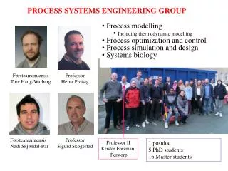
Miniature Engineering Systems GroupCore Group of Faculty Dr. Louis ChowDirector System design, spray cooling, thermal management, thermalfluids design/experiment,thermodynamics Dr. Jay KapatCo-Director System design, design of turbo machinery, heat transfer and fluidic components, component and system testing Dr. Quinn ChenAssociate Director for Educational Programs Micro-fabrication and tribology, actuators Dr. Linan An Polymer-derived ceramic micro-fabrication Dr. Chan Ham Control, micro-satellites Dr. K.B. Sundaram Micro-fabrication, thin film, sensors, micro- and meso-scale motors and generators Dr. Tom Wu RF MEMS, miniature electromagnetic devices Dr. Neelkanth Dhere Tribological coatings, multilayer thin films, sensors Dr. Joe Cho Bio-MEMS, Magnetic MEMS, MOEMS, micro/nano fabrication, micro fluidics
Outline of the presentation • Introduction, • Compressor design and CFD analysis, • Development of Gas Foil Bearings, • Motor design, • Work in progress, • Work to be completed by Sep ’03, • Plans for next year.
System Performance • Top cycle is capable of removing heat at liquid Nitrogen temperature with cooling power ~ 1000 W • 2-stage RTBC cycle is capable of removing heat at liquid Hydrogen temperature with cooling power ~ 50W • COP ~ 0.007
Design Features • Top cycle can work separately as a liquid nitrogen cryocooler; or it can work with bottom cycle as a liquid hydrogen cryocooler. • State-of-the-art aerodynamics design of the 2-stage intercooled neon centrifugal compressor and the 4-stage intercooled helium centrifugal compressor. • Integrated motor and oil-free non-contact bearings for high speed and efficiency. • Innovative micro-channel high effectiveness heat exchanger.
Schematic of the bottom cycle showing the four stage Helium compressor
Single Stage Centrifugal Compressor Development Motor Coupler Compressor
Single Stage Compressor • Three of the parts are still to be manufactured. • Impeller • Diffuser • Inlet Guide Vane • Plastic models have been created showing conceptual idea. • Rest of the compressor and the experimental set-up has been constructed. • Motor and brackets, as well as cooling jacket for motor • Compressor housing and brackets
Parts not fabricated yet… Impeller Diffuser Inlet Guide Vane
Future of Compressor Development • Machine the diffuser and inlet guide vane, and cast the impeller. • Assemble compressor and begin tests at low speeds to allow for break-in of bearings. • Test at maximum design speed of 150,000 revolutions per minute and collect data.
CFD SIMULATION OF IGV Fully Structured 3D Grid (Created in GAMBIT, 330K)
Reverse flow occurs at outlet of IGV. (Solved by Fluent 6.0)
CFD-IGV CFD simulation results show that pressure loss through IGV is about 5000 Pa. As expected, IGV creates an acceptable flow angle at the eye of impeller. However, certain amount of reverse flow still exists in spite of careful design. This may be eliminated by the interaction of IGV and rotor, which would be simulated in the next stage. If the flow reversal still persists, IGV design will be modified by adjusting angle of IGV vanes.
DEVELOPMENT OF GAS-FOIL BEARINGS Phases • Pro-art search (gave no favorable result), • Conceptual Design (of first generation Leaf Foil Bearings), • Modeling and Analysis, • Detailed design for fabrication and testing.
CONCEPTUAL DESIGN CONFIGURATION • It contains an outer hollow cylinder to which the foils are attached. • An inner hollow cylinder would have long cut grooves extending to about 90% of its length through which the foils would pass and hold the shaft in position during start-up and at stop. • The outer hollow cylinder can be rotated about the shaft center axis of rotation and the rotation of which would cause the foils to lose contact with the shaft thus making the same bearing as ‘Gas Bearing’ and also as a ‘Gas Foil Bearing’.
CONCEPTUAL DESIGNS FOR VARIOUS COMPONENTS FOLLOWED BY THE ASSEMBLY
Specifications of the Motor • The motor efficiency needs to be as high as possible. • Size and weight are also important issues.
Some Popular Motor Types • Induction motor (IM) : low cost, but low efficiency at high speed due to higher iron loss. • Switched reluctance motor (SRM): high reliability, but iron loss is very critical at high speed. • Permanent magnet synchronous motor (PMSM): very high efficiency due to no exciting copper loss in the rotor. High power density with high energy density permanent magnet Nd-Fe-B. • Brushless DC motor (BLDC): high power density as PMSM, but the large harmonics will reduce efficiency significantly at high speed.
Radial Flux PMSM Structure Shaft Stator Outer Diameter = 30mm Stator Inner Diameter = 23mm Rotor Diameter = 14mm PM Width = 6mm PM Height = 9mm Motor Active Length = 70mm PM Winding Laminated low loss core
Winding Method • 2-pole, 3-phase. • 5 coils/phase/pole. • Two layer lap winding. • Pitch factor: 12/15. • First coil: bottom1top13. • Round copper wire – AWG14. • Bare diameter: 0.0641in (1.63mm). • Diameter after insulation: 0.0673in (1.71mm).
Simulated Results Flux Distribution FFT Back EMF FFT Simulated torque =0.11N.m and ripple =0.3%, when 25A phase current. Very low harmonics in the air gap flux distribution and back EMF voltage.
Work in progress • Design of shaft/rotor for the system. • Minor changes to motor design basing on the shaft design.
Work to be completed by Sep’03 • One Stage Compressor – testing and simulation. • Design of the four stage helium compressor. • Motor – not integrated with compressor this year. • Gas Foil Bearings – Mathematical modeling and Analysis with simultaneous focus on tribological coatings to be deposited on foils.
Plans for next year • Fabrication and testing of the four stage helium compressor for the bottom cycle. It would be an integrated compressor-motor system. • Development of the micro-channel high effectiveness heat exchanger.