Download
1 / 25
820 likes | 2.17k Views
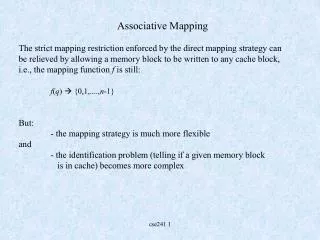
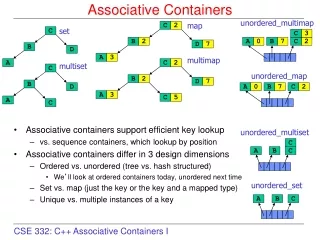
Associative Mapping. A main memory block can load into any line of cache Memory address is interpreted as tag and word Tag uniquely identifies block of memory Every line’s tag is examined for a match Cache searching gets expensive. Fully Associative Cache Organization.

E N D
Associative Mapping • A main memory block can load into any line of cache • Memory address is interpreted as tag and word • Tag uniquely identifies block of memory • Every line’s tag is examined for a match • Cache searching gets expensive
Comparison Direct Cache Example: 8 bit tag 14 bit Line 2 bit word Associate Cache Example: 22 bit tag 2 bit word
Set Associative Mapping • Cache is divided into a number of sets • Each set contains a number of lines • A given block maps to any line in a given set • e.g. Block B can be in any line of set i • e.g. 2 lines per set • 2 way associative mapping • A given block can be in one of 2 lines in only one set
Comparison Direct Cache Example: 8 bit tag 14 bit line 2 bit word Associate Cache Example: 22 bit tag 2 bit word Set Associate Cache Example: 9 bit tag 13 bit set 2 bit word
Replacement Algorithms (1)Direct mapping • No choice • Each block only maps to one line • Replace that line
Replacement Algorithms (2)Associative & Set Associative • Hardware implemented algorithm (speed) • First in first out (FIFO) • replace block that has been in cache longest • Least frequently used (LFU) • replace block which has had fewest hits • Random
Write Policy Challenges • Must not overwrite a cache block unless main memory is correct • Multiple CPUs may have the block cached • I/O may address main memory directly ? (may not allow I/O buffers to be cached)
Write through • All writes go to main memory as well as cache (Only 15% of memory references are writes) Challenges: • Multiple CPUs MUST monitor main memory traffic to keep local (to CPU) cache up to date • Lots of traffic – may cause bottlenecks • Potentially slows down writes
Write back • Updates initially made in cache only (Update bit for cache slot is set when update occurs – Other caches must be updated) • If block is to be replaced, memory overwritten only if update bit is set (Only 15% of memory references are writes ) • I/O must access main memory through cache or update cache
Coherency with Multiple Caches • Bus Watching with write through 1) mark a block as invalid when another cache writes back that block, or 2) update cache block in parallel with memory write • Hardware transparency (all caches are updated simultaneously) • I/O must access main memory through cache or update cache(s) • Multiple Processors & I/O only access non-cacheable memory blocks
Choosing Line (block) size • 8 to 64 bytes is typically an optimal block (obviously depends upon the program) • Larger blocks decrease number of blocks in a given cache size, while including words that are more or less likely to be accessed soon. • Alternative is to sometimes replace lines with adjacent blocks when a line is loaded into cache. • Alternative could be to have program loader decide the cache strategy for a particular program.
Multi-level Cache Systems • As logic density increases, it has become advantages and practical to create multi-level caches: 1) on chip 2) off chip • L1 (on chip) & L2 (off chip) caches • L2 cache may not use system bus to make caching faster • If L2 does not use the system bus, it can potentially be moved into the chip • Contemporary designs are now incorporating an on chip(s) L3 cache
Split Cache Systems • Split cache into: 1) Data cache 2) Program cache • Advantage: Likely increased hit rates – data and program accesses display different behavior • Disadvantage Complexity • Impact of Superscaler machine implementation ? (Multiple instruction execution, prefetching)
Processor Type Year of Introduction Primary cache (L1) 2nd level Cache (L2) 3rd level Cache (L3) IBM 360/85 Mainframe 1968 16 to 32 KB — — PDP-11/70 Minicomputer 1975 1 KB — — VAX 11/780 Minicomputer 1978 16 KB — — IBM 3033 Mainframe 1978 64 KB — — IBM 3090 Mainframe 1985 128 to 256 KB — — Intel 80486 PC 1989 8 KB — — Pentium PC 1993 8 KB/8 KB 256 to 512 KB — PowerPC 601 PC 1993 32 KB — — PowerPC 620 PC 1996 32 KB/32 KB — — PowerPC G4 PC/server 1999 32 KB/32 KB 256 KB to 1 MB 2 MB IBM S/390 G4 Mainframe 1997 32 KB 256 KB 2 MB IBM S/390 G6 Mainframe 1999 256 KB 8 MB — Pentium 4 PC/server 2000 8 KB/8 KB 256 KB — IBM SP High-end server/ supercomputer 2000 64 KB/32 KB 8 MB — CRAY MTAb Supercomputer 2000 8 KB 2 MB — Itanium PC/server 2001 16 KB/16 KB 96 KB 4 MB SGI Origin 2001 High-end server 2001 32 KB/32 KB 4 MB — Itanium 2 PC/server 2002 32 KB 256 KB 6 MB IBM POWER5 High-end server 2003 64 KB 1.9 MB 36 MB CRAY XD-1 Supercomputer 2004 64 KB/64 KB 1MB — Comparison of Cache Sizes a Two values seperated by a slash refer to instruction and data caches b Both caches are instruction only; no data caches
Problem Solution Processor on which feature first appears External memory slower than the system bus. Add external cache using faster memory technology. 386 Increased processor speed results in external bus becoming a bottleneck for cache access. Move external cache on-chip, operating at the same speed as the processor. 486 Internal cache is rather small, due to limited space on chip Add external L2 cache using faster technology than main memory 486 Contention occurs when both the Instruction Prefetcher and the Execution Unit simultaneously require access to the cache. In that case, the Prefetcher is stalled while the Execution Unit’s data access takes place. Create separate data and instruction caches. Pentium Increased processor speed results in external bus becoming a bottleneck for L2 cache access. Create separate back-side bus that runs at higher speed than the main (front-side) external bus. The BSB is dedicated to the L2 cache. Pentium Pro Move L2 cache on to the processor chip. Pentium II Some applications deal with massive databases and must have rapid access to large amounts of data. The on-chip caches are too small. Add external L3 cache. Pentium III Move L3 cache on-chip. Pentium 4 Intel Cache Evolution
Intel Caches • 80386 – no on chip cache • 80486 – 8k using 16 byte lines and four way set associative organization • Pentium (all versions) – two on chip L1 caches • Data & instructions • Pentium 3 – L3 cache added off chip • Pentium 4 • L1 caches • 8k bytes • 64 byte lines • four way set associative • L2 cache • Feeding both L1 caches • 256k • 128 byte lines • 8 way set associative • L3 cache on chip
Pentium 4 Core Processor • Fetch/Decode Unit • Fetches instructions from L2 cache • Decode into micro-ops • Store micro-ops in L1 cache • Out of order execution logic • Schedules micro-ops • Based on data dependence and resources • May speculatively execute • Execution units • Execute micro-ops • Data from L1 cache • Results in registers • Memory subsystem • L2 cache and systems bus
Pentium 4 Design Reasoning • Decodes instructions into RISC like micro-ops before L1 cache • Micro-ops fixed length • Superscalar pipelining and scheduling • Pentium instructions long & complex • Performance improved by separating decoding from scheduling & pipelining • (More later – ch14) • Data cache is write back • Can be configured to write through • L1 cache controlled by 2 bits in register • CD = cache disable • NW = not write through • 2 instructions to invalidate (flush) cache and write back then invalidate • L2 and L3 8-way set-associative • Line size 128 bytes
PowerPC Cache Organization (Apple-IBM-Motorola) • 601 – single 32kb 8 way set associative • 603 – 16kb (2 x 8kb) two way set associative • 604 – 32kb • 620 – 64kb • G3 & G4 • 64kb L1 cache • 8 way set associative • 256k, 512k or 1M L2 cache • two way set associative • G5 • 32kB instruction cache • 64kB data cache