Download
1 / 31
320 likes | 491 Views
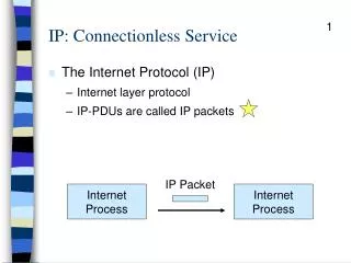
IP: Connectionless Service. The Internet Protocol (IP) Internet layer protocol IP-PDUs are called IP packets. IP Packet. Internet Process. Internet Process. IP: Connectionless Service. Connectionless Just send the packet No host or network overhead to open, close connections

E N D
IP: Connectionless Service • The Internet Protocol (IP) • Internet layer protocol • IP-PDUs are called IP packets IP Packet Internet Process Internet Process
IP: Connectionless Service • Connectionless • Just send the packet • No host or network overhead to open, close connections • Not host or network overhead due to Acks • No error handling. (Let TCP catch errors!) IP Packet Internet Process Internet Process
TCP-IP Partnership in Error Handling • TCP checks for errors once, at the destination host • IP does not have to check on each hop between routers • More efficient overall Check Only Once Transport Transport Internet Internet Internet Host Router Host
Connectionless IP • IP is unreliable (does not catch errors) • But this is not bad • First, errors are caught--at the next-higher layer (transport) if TCP is used • Second, avoiding error checking at each hop between routers lowers router costs
IP is a Best-Effort Service • IP Only Offers Best-Effort Service • Does its best to get packets through • No guarantees of delivery • No way to give priority to time-sensitive traffic, such as voice • Overall, low overhead but limited Quality of Service (QoS) • This should change in the future (see Module A)
Internet Addresses • Also called IP addresses • Example: 128.171.17.13 • Really 32-bit strings of ones and zeros • Fit into source and destination address fields of IP headers IP Packet 32-bit Source and Destination Addresses
Internet Address • Hierarchical Addressing • Two-Parts • Network part (organization on the Internet) • Local part (host on the network) • Three-Parts • Network (organization on the Internet) • Subnet (suborganization) • Host on the subnet
Internet Addresses • Two-Part • Divide 32-bit Internet address into two parts • First part designates the network • Second (local) part designates the host on the network • Example: Network Part 128.171.17.13 Local Part
Internet Addresses • Three-Part • Local part is subdivided • Subnet part designates the subnet (suborganization) • Host part designates the host • Example: Network Part Host Part 128.171.17.13 Subnet Part
2-Part Internet Address and Routers • Source host (Host 1) is 128.171.15.12 • On network 128.171 • Has packet for host 128.171.9.6 Network 128.171 Host 2 128.171.9.6 128.171.9.6 Host 1128.171.15.12
2-Part Internet Address and Routers • Source host compares network part of destination address to its own • Match (128.171), so destination host must be on the source host’s own network Network 128.171 Host 2 128.171.9.6 128.171.9.6 Host 1128.171.15.12
2-Part Internet Address and Routers • Source host delivers the IP packet directly to the destination host New: Direct Delivery is not Discussed in the Book Network 128.171 Host 2 128.171.9.6 128.171.9.6 Host 1128.171.15.12
2-Part Internet Address and Routers • Source host (Host 1) has packet for 127.27.180.6 • Destination host’s network part (127.27) does not match source host’s network part (128.171), so Host 1 cannot deliver the packet directly. Host 1 sends the packet to Router A. Network 128.171 Router A 128.171.93.15 Router B 127.27.9.12 127.27.180.6 Router A 127.27.7.7 Host 1128.171.15.12 Host 3 127.27.180.6
2-Part Internet Address and Routers • Router A • Has a separate address on each network that it connects • 128.171.93.15 and 127.27.7.7 Network 128.171 Router A 128.171.93.15 Router B 127.27.9.12 127.27.180.6 Router A 127.27.7.7 Host 1128.171.15.12 Host 3 127.27.180.6
2-Part Internet Address and Routers • Router A Considers the packet • Router A looks at destination address network part ONLY (127.27) • Compares to network parts of its own addresses (128.171, 127.27). Match on 127.27. Network 128.171 Router A 128.171.93.15 Router B 127.27.9.12 127.27.180.6 Router A 127.27.7.7 Host 1128.171.15.12 Host 3 127.27.180.6
2-Part Internet Address and Routers • Router A Delivers the IP Packet • Destination host is on 127.27. • Router A delivers the packet Network 128.171 Router A 128.171.93.15 Router B 127.27.9.12 127.27.180.6 Router A 127.27.7.7 Host 1128.171.15.12 Host 3 127.27.180.6
2-Part Internet Address and Routers • If no network part matches • Destination host is not on one of Router A’s networks • Router A passes the IP packet onto another router (Router B) Network 128.171 Router A 128.171.93.15 Router B 127.27.9.12 Router A 127.27.7.7 Host 1128.171.15.12 Host 3 127.27.180.6
3-Part Internet Address and Routers • Routers attach to multiple subnets (not networks) • Has an internet address on each subnet • Network PLUS subnet part underlined Network/Subnet 127.171.17 Router A 127.171.17.15 Router B 127.171.15.12 Router A 127.171.15.7 Host 1127.171.17.12 Host 3 127.171.15.6
3-Part Internet Address and Delivery New: Case Not Discussed in Book • Case 1: Source host looks at network+subnet part of destination IP address • Destination IP address is 127.171.17.33 • Source host’s IP address is 127.171.17.12 • Source host compares network+subnet parts • They match • So destination host is on source host’s subnet • Source host sends the IP packet directly to the destination host
3-Part Internet Address and Delivery • Case 2: Source host looks at network+subnet part of IP addresses • Destination IP address is 127.171.15.33 • Source host’s IP address is 127.171.17.12 • Source host compares network+subnet parts • They do not match • So destination host is NOT on source host’s subnet • Source host sends the IP packet to a router
3-Part Internet Address and Delivery • Case 2: Continued • Destination IP address is 127.171.15.33 • Router is on 127.171.17 and 127.171.15 • 127.171.15 is a match • So destination host is on that subnet • Router delivers the IP packet to Host 3 (127.171.15.33) on that subnet
3-Part Internet Address and Delivery • Case 3 • Destination IP address is 127.171.47.33 • Router is on 127.171.17 and 127.171.15 • There is no network+subnet match • So destination host is not on any of the router’s subnets • Router passes the IP packet for 127.171.47.33 to another router for delivery
IP Packet Header • Shown in rows of 32 bits each • Error in the book’s first edition (line beginning “Time to Live” is missing in first printing) Bit 0 Bit 31 Version (4) Hdr Len (4) TOS (8) Total Length in bytes (16) Indication (16 bits) Flags (3) Fragment Offset (13) Time to Live (8) Protocol (8) Header Checksum (16) Source IP Address Destination IP Address Options (if any)
IP Packet Header • Version • Version number of IP protocol • Current version is Version 4 (No 1, 2, or 3 were used) • Moving to Version 6 (No 5 was used) • Version 4 Header shown Bit 0 Bit 31 Version (4) Hdr Len (4) TOS (8) Total Length in bytes (16) Indication (16 bits) Flags (3) Fragment Offset (13) Time to Live (8) Protocol (8) Header Checksum (16) Source IP Address Destination IP Address Options (if any)
IP Packet Header • Type of Service (TOS) • Allows different types of service to be requested • Initially, meaning was not defined well • Currently being defined Bit 0 Bit 31 Version (4) Hdr Len (4) TOS (8) Total Length in bytes (16) Indication (16 bits) Flags (3) Fragment Offset (13) Time to Live (8) Protocol (8) Header Checksum (16) Source IP Address Destination IP Address Options (if any)
IP Packet Header Not shown in book’s first printing • Time to Live • Initially set by sending host transport process • Up to 255 • Decremented by each router • At 0, discarded to avoid infinite loops Bit 31 Version (4) Hdr Len (4) TOS (8) Total Length in bytes (16) Indication (16 bits) Flags (3) Fragment Offset (13) Time to Live (8) Protocol (8) Header Checksum (16) Source IP Address Destination IP Address Options (if any)
IP Packet Header Not shown in book’s first printing • Protocol • Value indicates what is in the data field • TCP-PDU is only one possibility Bit 0 Bit 31 Version (4) Hdr Len (4) TOS (8) Total Length in bytes (16) Indication (16 bits) Flags (3) Fragment Offset (13) Time to Live (8) Protocol (8) Header Checksum (16) Source IP Address Destination IP Address Options (if any)
IP Packet Header Not shown in book’s first printing • Header Checksum • Checks for error in the header only • Bad headers can harm the network • Very little work compared to checking the entire packet • If error found, packet is simply discarded Bit 31 Version (4) Hdr Len (4) TOS (8) Total Length in bytes (16) Indication (16 bits) Flags (3) Fragment Offset (13) Time to Live (8) Protocol (8) Header Checksum (16) Source IP Address Destination IP Address Options (if any)
IP Packet Header • Source and Destination IP Addresses • Strings of 32 ones and zeros Bit 0 Bit 31 Version (4) Hdr Len (4) TOS (8) Total Length in bytes (16) Indication (16 bits) Flags (3) Fragment Offset (13) Time to Live (8) Protocol (8) Header Checksum (16) Source IP Address Destination IP Address Options (if any)
IP Packet Header • Options • Rarely Used in Version 4 Bit 0 Bit 31 Version (4) Hdr Len (4) TOS (8) Total Length in bytes (16) Indication (16 bits) Flags (3) Fragment Offset (13) Time to Live (8) Protocol (8) Header Checksum (16) Source IP Address Destination IP Address Options (if any)
Data Link Layer Process • Internet layer process passes EACH IP packet to the data link layer process for delivery over the data link Internet LayerProcess IP Packet Data Link LayerProcess