Download
1 / 35
360 likes | 428 Views
Learn about Verilog, a Hardware Description Language, syntax, semantics, and examples. Explore Verilog installation, test bench programs, and key concepts.

E N D
Introduction to Veriloghttp://web.sonoma.edu/users/k/kujoory/course_materials/es_210/ Department of Engineering ScienceES210L Digital Circuit & Logic Design Lab References • "Digital Design,” Morris Mano and Michael Ciletti, 5th ed, Pearson, 2012. • MobaXtermhttp://www.sonoma.edu/engineering/resources/remote.html • http://www.referencedesigner.com/tutorials/verilog/verilog_01.php • http://www.ece.umd.edu/class/enee359a/verilog_tutorial.pdf • http://www.sonoma.edu/esee/courses/jack_ou/cadence/ • http://www.asic-world.com/verilog/verilog_one_day1.html#Introduction
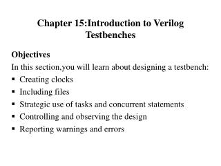
Topics Covered • What is Verilog • Verilog HDL Syntax and Semantics • Environment • Verilog Design File Examples • Verilog Test Bench File Examples • Verilog Installation and Installing MobaXterm • Running Verilog Simulation HDL = Hardware Description Language
What is Verilog • Verilog (IEEE 1364) is a Hardware Description Language (HDL) • HDL is a programming language that uses codes to describe & model digital circuits • VHDL (IEEE 1076) is another example of HDL • Verilog allows to simulate digital circuits and displays the output vs input waveforms and propagation time before building them • Digital circuits can be complex when making ICs • Verilog HDL was designed by Phil Moorby, who later became the Chief Designer for Verilog-XL and the first Corporate Fellow at Cadence Design Systems. https://en.wikipedia.org/wiki/Veriloghttp://www.verilog.com IC=integrated circuits http://www.electronicdesign.com/what-s-difference-between/what-s-difference-between-vhdl-verilog-and-systemverilog
Example of a Circuit and Verilog Output View Verilog Design program Describes the logic circuit Test bench program specifies instances of the inputs
Two Verilog Programs Needed //fig3p37.v (Verilog Design Prog) // Defines the digital circuit modulefig3p37 (A,B,C,D,E); outputD,E; inputA,B,C; wirew1; andG1(w1,A,B); notG2(E,C); orG3(D,w1,E); endmodule //fig3p37_tb.v (Test bench program) // Specifies instances of inputs `timescale 1 ms / 1 us `include "fig3p37.v" module fig3p37_tb; wire D,E; regA,B,C; fig3p37 M1(A,B,C,D,E); //Instance name initial begin A =1'b0; B =1'b0; C =1'b0; #100 A =1'b1; B =1'b1; C =1'b1; end initial #200 $finish; endmodule
Verilog HDL Syntax and Semantics • White spaces are ignored- characters that contain white space: • blanks, tabs, newlines, and form feeds • Case sensitive: Lower case letters are unique from upper case letters • All Verilog keywords are lower case • Identifiers are names used to identify an object • e.g., a register, a function, or a module • A name so that it can be referenced from other places in a description. • Identifiers may contain alphabetic characters, numeric characters, the underscore, and the dollar sign (a−z, A−Z, 0−9, $, or _ ) • But must begin with an alphabetic character or the underscore character (a−z,A−Z, or _ ) • Can be up to 1024 characters long. • Examples of legal identifiers • data_inputmu • clk_inputmy$clk • i386 A
Example of Bad and Good Codes Bad Code (although correct): • moduleaddbit(a,b,ci,sum,co); • inputa,b,ci;output sum co; • wirea,b,ci,sum,co;endmodule Good Code • moduleaddbit ( • a, • b, • ci, // Carry In • sum, • co; // Carry Out • ); • input a; • input b; • input ci; • output sum; • output co; • wire a; • wire b; • wire ci; • wire sum; • wire co;- • endmodule
Sample Program 1 “hello_world” • //−−−−−−−−−−−−−−−−−−−−−−−−−− • // This is my first Verilog Program • // Design Name: hello_world • // File Name: hello_world.v • // Function: This program prints 'hello world’ • // Coder: Deepak • //−−−−−−−−−−−−−−−−−−−−−−−−−− • modulehello_world; • // • initial begin • $display( "Hello World by Deepak" ); • #10 $finish; • end • endmodule// End of Module hello_world • Green words represent comments • “//” starts a comment line • Blue words represent reserved keywords • Lines 8 & 14 start & end a module • Lines 10 to 13 contains initialblock that begin & end the block. • The module gets executed at time=0 (0 ms) Output of the program is: Hello World by Deepak
Examples of Comments • /* This is a • Multi line comment • example */ • moduleaddbit( • a, • b, • ci, • sum, • co); • a=4’b1010 • Single line comments begin with token // and end with a carriage return • Multi Line comments • begin with the token /* and • end with the token */ • Number spec notation: <size in bits>’ <base> <number value>, e.g., 4’b1010is a 4-bit binary value 1010 16’h6cdais a 16 bit hex number with value 6cda 8’d40 decimal value 40 Start with /* End with */
Examples of Comments • // Input Ports, Single line comment • module example; • inputa; • inputb; • inputci; • // Output ports • output sum; • outputco; • // Data Types • wire a; • wireb; • wireci; • wiresum; • wireco; • endmodule
Set Up the Environment • Assuming that you want to have a library folder for es210 for your Verilog files and simulation files on the Cadence server that you have an account. • Open a terminal. [kujoory@cadence ~]$ mkdir es210 [kujoory@cadence ~]$ cd es210 • We can make a Verilog file fig3p37.v in the es210 folder in cadence server [kujoory@cadence ~]$ es210/fig3p37.v • Cadence Design Systemsis an American Electronic Design Automation(EDA) software and engineering services company that produces software and hardware for designing integrated circuits, systems on chips (SoCs) &printed circuit boards. • circuit simulation, is an EDA product for and FPGAdesigns. https://en.wikipedia.org/wiki/Cadence_Design_Systems $character is a prompt in Verilog
Your First Verilog Program A Verilog program describes the digital circuit. module fig3p37 (A,B,C,D,E); output D,E; input A,B,C; wire w1; and G1(w1,A,B); not G2(E,C); or G3(D,w1,E); endmodule fig3p37 is the name of the module Words in blue are keywords
module....endmodule module fig3p37 (A,B,C,D,E); output D,E; input A,B,C; wire w1; and G1(w1,A,B); not G2(E,C); or G3(D,w1,E); endmodule An example of a Verilog Design program fig3p37is the name of the module Always start the Verilog program with the keyword pairmodule…endmodule The keywordmodule must always be terminated by the keyword endmodule. Each line here is a statement.
Keywords module fig3p37 (A,B,C,D,E); output D,E; input A,B,C; wire w1; and G1(w1,A,B); not G2(E,C); or G3(D,w1,E); endmodule Each statement ends with a semicolon
Primitive Gates module fig3p37 (A,B,C,D,E); output D,E; input A,B,C; wire w1; and G1(w1,A,B); not G2(E,C); or G3(D,w1,E); endmodule and, not,or are primitive gates The output is listed first The inputs and outpts can be listed in any order G1 is an instance of the and gate
“assign” keyword • “assign” keyword can also be used to assign a value to the output • It is followed by a Boolean expression • To distinguish arithmetic operators from logical operators, • Verilog uses symbols “&”, “|”, and “~” for AND, OR, and NOT, respectively, e.g., See Examples 4.3, 4.4, and 4.5 in textbook by Mano
Table 4.10Some Verilog HDL Operators Complete list in Table 8.1 & https://www.utdallas.edu/~akshay.sridharan/index_files/Page5212.htm Equal by value, e.g., 111=111 = for logical assign
Set Up the Testbench • In addition to Verilog design program, we need a test bench program to define the instances (in time) of inputs that we apply to the circuit to get the outputs
Test Bench Module //fig3p37.v is Verilog Design file modulefig3p37 (A,B,C,D,E); outputD,E; inputA,B,C; wirew1; andG1(w1,A,B); notG2(E,C); orG3(D,w1,E); endmodule //fig3p37_tb.v is test bench program file `timescale 1 ms / 1 us `include "fig3p37.v" module fig3p37_tb; wire D,E; reg A,B,C; fig3p37 M1(A,B,C,D,E); //Instance name initial begin A =1'b0; B =1'b0; C =1'b0; #100 A =1'b1; B =1'b1; C =1'b1; end initial #200 $finish; endmodule “fig3p37.v” identifies design program with file type “v” below fig3p37_tb is the module name for the test bench program “tb” indicates test bench M1 is the instance of the module, required. Fig3p37 is the main or associated module name (below)
Test Bench Module //fig3p37_tb.v (test bench) file `timescale 1 ms / 1 us `include "fig3p37.v" module fig3p37_tb; wire D,E; reg A,B,C; fig3p37 M1(A,B,C,D,E); //Instance name initial begin A =1'b0; B =1'b0; C =1'b0; #100 A =1'b1; B =1'b1; C =1'b1; end initial #200 $finish; endmodule (`) is a back apostrophe before timescale and include “1 ms” specifies the unit of measurement for delays “1 us” specifies the precision for which delays are rounded off In Test Bench program the circuit outputs are declared with keyword wireand inputs with keyword reg The initialkeyword is used with a set of statements that begin executing when the simulation is initialized begin….end The statements are executed in sequence from top to bottom
Test Bench Module //fig3p37_tb.v (test bench) file `timescale 1 ms / 1 us `include "fig3p37.v" module fig3p37_tb; wire D,E; reg A,B,C; fig3p37 M1(A,B,C,D,E); //Instance name initial begin A =1'b0; B =1'b0; C =1'b0; #100 A =1'b1; B =1'b1; C =1'b1; end initial #200 $finish; endmodule # specifies the delay in the number of time units Format for variable: size/’/base/value e.g., A is one binary bit with a value of 1 # 200 specifies the duration for the display
MobaXterm Installation You should have an account on Cadence/Verilog server by emailing Mr. Shahram Marivani (marivani@sonoma.edu) • Insert your flash memory into the Lab PC or your laptop • Go to http://www.sonoma.edu/engineering/ and click on Resources • Click on Remote Server Access • Follow the instruction of MobaXterm for Windows or MAC computer • MobaXterm opens a Terminal page for Windows7 as in Linux • For Windows, click on MobaXterm • You want to install this application on a flash memory so that you can use it in the lab or any computer including your laptop • MobaXterm initiates a secure shell (ssh) session to communicate with the server • On “Home Edition” page click on “Download now” • Click “Mobaterm Home Edition” and “Download Now” • Select “MobaXterm Home Edition v11.0 (Portable edition)” and download zip file on the flash memory • Double click on the file, select MobaXterm_Personal_v11.0.exeand RUN it
MobaXterm for Windows • As the MobaXtermwindow opens, you should see a display as shown • Click Session at left top corner • Select SSH at left top corner • In Remote host, type the IP address 130.157.3.118 in the box • Check “Specify username” • Enter your Seawolf User name in the box & click OK. • Login using your Seawolf password • A Terminal (Linux) window opens for the Verilog • At this time you can access/build your Verilog directory & programs • E.g. es210/fig3p37.v • To run enterverilog +guifig3p37.v
XQuartz and Xterm for MacBook • You need to download “XQuartz for MAC” • A Terminal (Linux) page opens • At the promp, type ssh -Y your_seawolf_username@130.157.3.118 • Enter your Seawolfpassword • At this time you can access/build your Verilog folders and programs • E.g. es210/fig3p37.v
Terminal Display – Example 1 • Make a folder for es210 on the Terminal page • Use a Linux editor such as vi to make a verilog design file, e.g., fig3p37.v that describes the desired digital circuit • Then, forfig3p37 circuit shown, the location of the Verilog design file is es210/fig3p37.v (The verilogsandbox folder in terminal display is removed for simplification) • We need also to make a test benchfile that defines the desired instances of inputs to apply to the circuit as es210/fig3p37_tb.v • The figure below shows a typical Terminal display. • Next slide shows the Verilog files
Verilog Files for – Example 1 onfig3p37 //fig3p37_tb.v is the test bench file `timescale 1 ms / 1 us `include "fig3p37.v" modulefig3p37_tb; wire D,E; regA,B,C; fig3p37 M1(A,B,C,D,E); //Instance name initial begin A =1'b0; B =1'b0; C =1'b0; #100 A =1'b1; B =1'b1; C =1'b1; end initial#200 $finish; endmodule //fig3p37.v is the design file module fig3p37 (A,B,C,D,E); output D,E; input A,B,C; wire w1; and G1(w1,A,B); not G2(E,C); or G3(D,w1,E); endmodule
Verilog for Simulation – Example 1 • Compiling and running the Verilog file can simulate the circuit and display the input and output waveforms related to test bench data in fig3p37_tb.v • To compile the file, TYPE verilog fig3p37_tb.v and ENTER • fig3p37.v and fig3p37_tb.v files will be first checked for syntax errors, and • fig3p37.v is processed before the digital waveforms are displayed • The file compilation is complete when there are no errors • To run the program, at the prompt, TYPE verilog +gui fig3p37_tb.v and hit ENTER Note: There are two ways to compile the files: • Make two separate files (preferred): • fig3p37.v and • one that starts with command `include fig3p37.v followed by the fig3p37_tb.v module, in which case you need to run the fig3p37_tb.v file (see next slide), or • Make one composite file that includes fig3p37_tb.v module followed by the fig3p37.v module (next slide, can skip)
Verilog Modules – Example 1 For a composite file, all “//” characters must to be removed.
Windows After Running fig3p37_tb.v File – Example 1 1. Go to “Simulation”. Select & click on “Reinvoke Simulator”. 2. Click “Yes” on the resulting Reinvoke tab & go to the lower screen. 3. Click on “+” sign to expand the subfolders & click on the “+” sign of MI to expand. You will see all the input/output entries in the right window. Select all these entries. 4. Go to this icon to “Send selected objects to the waveform”. The place- holder of the waveforms for all variables are displayed in a new screen on right. 5. Change time in “Time A” to 100 ms. Note that you need to change ussec scale to msec scale. 6. Go to “Simulation”. Select & click “Run”.
Windows After Running fig3p37_tb.v File – Example 1 • The waveforms of the input signals and the resulting outputs will be displayed in a window for a range. • To view the waveforms in the desired range, 0-200ms in this example, do the following. 7. Go to “Times” and enter the range to 0-200 ms for the waveforms & hit RETURN.to see all waveforms as shown 8. You can move the vertical line indicator on the waveforms to left & right by clicking on these arrows
Example 2: Simulate the Same Circuit with Different Inputs // Testbenchfig3p37 with different inputs `timescale 1 ms / 1 us `include "fig3p37.v" module fig3p37_tb; wire D,E; regA,B,C; fig3p37 M1(A,B,C,D,E); //Instance name initial begin A =1'b0; B =1'b0; C =1'b0; #100 A =1'b1; B =1'b1; C =1'b1; #50 A =1'b0; B =1'b0; C =1'b0; #100 A =1'b1; B =1'b1; C =1'b1; end initial #400 $finish; endmodule // commented module fig3p37 (A,B,C,D,E); // output D,E; // input A,B,C; // wire w1; // and G1(w1,A,B); // not G2(E,C); // or G3(D,w1,E); // endmodule