Download
1 / 1
10 likes | 118 Views
Structural Validation. Final Design. Finite Element Analysis. The design is a cantilever structure which supports the full weight of both totes. The design fits the tight and limited space constraints Once totes are in place requires little operator interaction. Minimum Factor of Safety

E N D
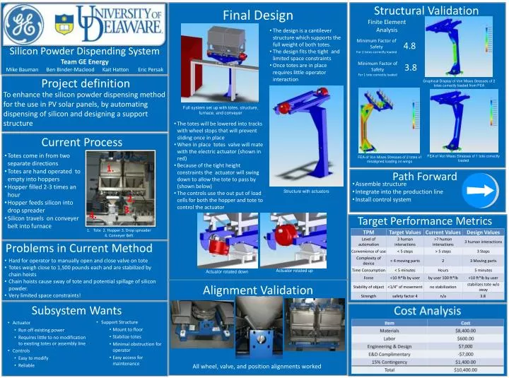
Structural Validation Final Design Finite Element Analysis • The design is a cantilever structure which supports the full weight of both totes. • The design fits the tight and limited space constraints • Once totes are in place requires little operator interaction Minimum Factor of Safety For 2 totes correctly loaded 4.8 Silicon Powder Dispending System Team GE Energy Mike Bauman Ben Binder-Macleod Kait Hatton Eric Persak Minimum Factor of Safety For 1 tote correctly loaded 3.8 Project definition Graphical Display of Von Mises Stresses of 2 totes correctly loaded from FEA To enhance the silicon powder dispensing method for the use in PV solar panels, by automating dispensing of silicon and designing a support structure Full system set up with totes, structure, furnace, and conveyer • The totes will be lowered into tracks with wheel stops that will prevent sliding once in place • When in place totes valve will mate with the electric actuator (shown in red) • Because of the tight height constraints the actuator will swing down to allow the tote to pass by (shown below) • The controls use the out put of load cells for both the hopper and tote to control the actuator Current Process • Totes come in from two separate directions • Totes are hand operated to empty into hoppers • Hopper filled 2-3 times an hour • Hopper feeds silicon into drop spreader • Silicon travels on conveyer belt into furnace FEA of Von Mises Stresses of 1 tote correctly loaded FEA of Von Mises Stresses of 2 totes of misaligned loading on wings 1. Path Forward • Assemble structure • Integrate into the production line • Install control system Structure with actuators 2. 3. 4. Target Performance Metrics • Tote 2. Hopper 3. Drop spreader • 4. Conveyer Belt Subsystem Wants Problems in Current Method • Support Structure • Mount to floor • Stabilize totes • Minimal obstruction for operator • Easy access for maintenance • Actuator • Run off existing power • Requires little to no modification to existing totes or assembly line • Controls • Easy to modify • Reliable • Hard for operator to manually open and close valve on tote • Totes weigh close to 1,500 pounds each and are stabilized by chain hoists • Chain hoists cause sway of tote and potential spillage of silicon powder. • Very limited space constraints! Actuator rotated up Actuator rotated down Alignment Validation All wheel, valve, and position alignments worked