Download
1 / 48
970 likes | 2.35k Views
Exploration, Sampling, and In Situ Soil Measurements. Dr. Omar Al-Hattamleh. Purpose of Soil Exploration. Information to determine the type of foundation required (shallow or deep).

E N D
Exploration, Sampling, and In Situ Soil Measurements Dr. Omar Al-Hattamleh
Purpose of Soil Exploration • Information to determine the type of foundation required (shallow or deep). • Information to allow the geotechnical consultant to make a recommendation on the allowable load capacity of the foundation. • Sufficient data/laboratory tests to make settlement predictions. • Location of the groundwater table (or determination of whether it is in the construction zone). For certain projects, groundwater table fluctuations may be required. These can require installation of piezometers and monitoring of the water level in them over a period of time.
Purpose of Soil Exploration Cont’ • Information so that the identification and solution of construction problems (sheeting and dewatering or rock excavation) can be made. • Identification of potential problems (settlements, existing damage, etc.) concerning adjacent property. • Identification of environmental problems and their solution.
Planning The Exploration Program • The subsurface exploration program in general comprises of three steps • Collection of primary data • Reconnaissance • Site Investigation
Collection of primary data • Assembly of all available information on: • dimensions, • column spacing, • type and use of the structure, • basement requirements, • any special architectural considerations of the proposed building, • and tentative location on the proposed site. • Foundation regulations in the local building code should be consulted for any special requirements.
Reconnaissance of the area • This may be in the form of: • a field trip to the site, which can reveal information • on the type and behavior of adjacent structures such • as cracks, • noticeable sags, • and possibly sticking doors and windows. • The type of local existing structures may influence to a considerable extent the exploration program and the best type of foundation for the proposed adjacent structure. • Since nearby existing structures must be maintained in their "as is" condition, • excavations or construction vibrations will have to be carefully controlled, and this can have considerable influence on the "type" of foundation that can be used.
Reconnaissance of the area Cont’ • Study of the various sources of information available, some of which include the following: • Geological maps. • Agronomy maps. • Aerial photographs. Investigator may require special training to interpret soil data, but the nonspecialist cannot easily recognize terrain features. Water and/or oil well logs. • Hydrological data. Data collected on streamflow data, tide elevations, and flood levels. • Soil manuals by state departments of transportation. • State (or local) university publications. These are usually engineering experiment station publications.
Site Investigation • A preliminary site investigation. In this phase a few borings (one to about four) are made or a test pit is opened to establish in a general manner the stratification, types of soil to be expected, and possibly the location of the groundwater table. If the initial borings indicate that the upper soil is loose or highly compressible, one or more borings should be taken to rock or competent strata. This amount of exploration is usually the extent of the site investigation for small structures. • A detailed site investigation. Where the preliminary site investigation has established the feasibility and overall project economics, a more detailed exploration program is undertaken. The preliminary borings and data are used as a basis for locating additional borings, which should be confirmatory in nature, and determining the additional samples required.
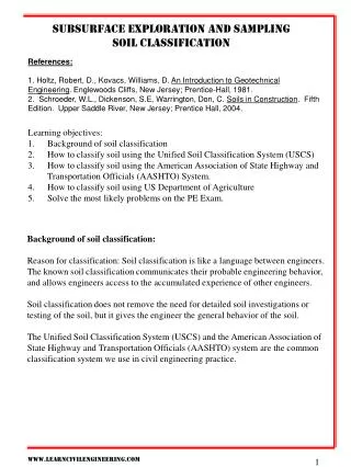
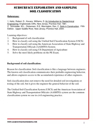
Methods Of Exploration • The most widely used method of subsurface investigation for compact sites as well as formost extended sites is boring holes into the ground, from which samples may be collected for either visual inspection or laboratory testing. • The several exploration methods for sample recovery • Disturbed samples taken • Undisturbed samples taken
Soil Boring • Exploratory holes into the soil may be made by • hand tools, • but more commonly truck- or trailer-mounted power tools are used
Hand Tools For Soil Exploration, • Hand augers
Gasoline-engine-powered Hand Auger gasoline-engine-powered hand auger with additional auger flights in the foreground together with hand-driven sample tube.
Flight Auger Bucket Auger.
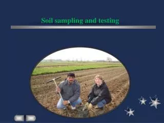
Soil Sampling • The most important engineering properties for foundation design are strength, compressibility, and permeability. • Needs undisturbed sample • The sample is always unloaded from the in situ confining pressures, with some unknown resulting expansion. Lateral expansion occurs into the sides of the borehole, so in situ tests using the hole diameter as a reference are "disturbed" an unknown amount. This is the reason K0 field tests are so difficult. • Samples collected from other than test pits are disturbed by volume displacement of the tube or other collection device. The presence of gravel greatly aggravates sample disturbance. • Sample friction on the sides of the collection device tends to compress the sample during recovery. Most sample tubes are (or should be) swaged so that the cutting edge is slightly smaller than the inside tube diameter to reduce the side friction.
Soil Sampling Continued • There are unknown changes in water content depending on recovery method and the presence or absence of water in the ground or borehole. • Loss of hydrostatic pressure may cause gas bubble voids to form in the sample. • Handling and transporting a sample from the site to the laboratory and transferring the sample from sampler to testing machine disturb the sample more or less by definition. • The quality or attitude of drilling crew, laboratory technicians, and the supervising engineer may be poor. • On very hot or cold days, samples may dehydrate or freeze if not protected on-site. Furthermore, worker attitudes may deteriorate in temperature extremes.
sample disturbance • Sample disturbance depends on factors such as • rate of penetration, • whether the cutting force is obtained by pushing or driving, • and presence of gravel, • it also depends on the ratio of the volume of soil displaced to the volume of collected sample, expressed as an area ratio where D0 — outside diameter of tube Di = inside diameter of cutting edge of tube Well-designed sample tubes should have an area ratio of less than about 10 percent.
sample disturbance • Another term used in estimating the degree of disturbance of a cohesive or rock core sample is the recovery ratio Lr A recovery ratio of 1 (recovered length of the sample = the length sampler was forced into the stratum) indicates that, theoretically, the sample did not become compressed from friction on the tube. A recovery ratio greater than 1.0 would indicate a loosening of the sample from rearrangement of stones, roots, removal of preload, or other factors.
Soil Testing Variety of Field Testing Devices 22
Standard Penetration Test Standard Penetration Test
SPT discrepancies (correction) • Equipment from different manufacturers. A large variety of drilling rigs are in current use; however, the rotary auger with the safety hammer of is the most common in North American practice (type of hammer). • Drive hammer configurations. The anvil also seems to have some influence on the amount of energy input to the sampler. • Whether a liner is used inside the split barrel sampler. Side friction increases the driving resistance (and AO and is less without the liner. It is common practice not to use a liner. Also it would appear that N values should be larger for soils with OCR > 1 (and larger relative density Dr) than for normally consolidated soils. borehole size) • Overburden pressure. Soils of the same density will give smaller TV values if p'o is smaller (as near the ground surface). Oversize boreholes on the order of 150 to 200 mm will also reduce N unless a rotary hollow-stem auger is used with the auger left in close contact with the soil in the hole bottom. Degree of cementation may also be significant in giving higher N counts in cemented zones that may have little overburden pressure. • Length of drill rod.
Correction SPT, N60 N60= SPT values corrected for field procedure H= hammer efficiency (table 2.2 Das) B= borehole diameter correction (table 2.2 Das) S= Sampler correction (table 2.2 Das) R= Rod length correction (table 2.2 Das ) N= Measured SPT N values (table 2.2 Das)
Correction SPT, (N1)60 N60: N corrected for field procedure (N1)60: N corrected for field procedure and overburden pressure
SPT Correlations Relative Density and Internal Friction Angle Eq. 2.11 & 2.13
SPT Correlations Empirical values for ,Dr and unit weight of granular soils based on the SPT at about 6 m depth and normally consolidated SPT (N1)60
(N60) Consistency of saturated cohesive soils K= (3.5-6.5 kN/m2) Water Table correction (drained vs undrained)
Cone Penetration Test Types of cones (Most common): (a) A mechanical cone (also known as a Begemann Cone); and (b) An electric cone [see Figure 2.12 & 2.13 page 69 Das]
CPT • Driving rate 10 to 20 mm/s • The tip (or cone) usually has a projected cross-sectional area of 10 cm2, • Friction sleeve area 150 cm2
Typical measurements See also Fig. 2.14 Das p 70
Correlation • With Relative density as Qc : compressibility factor ranges between 0.91 for High compressible sand (loose) to 1.09 law compressible sand (dense to very dense) • Internal Friction angle • Undrained Shear Strength, Cu ; NK Bearing capacity factor 15 for mechanical and 20 for electrical • Maximum past pressure and OCR as (MN/m2)
Classification of soil based on CPT test results See Figure 2.15 DAS p 71
Correlation between qc/N60 and the mean grain size, D50. See Figure 2.16 DAS p 72
Vane Shear Test FIELD VANE SHEAR TESTING (FVST)
Data Reduction undrained shear strength Cu=T/K K=366x10-8D3;D(cm) Cu=Cu(VST) =1.7-0.54log(PI%) or use Figure 2.11 in text page 67
ROCK SAMPLING • blow counts areat the refusal level (N > 100)Use Rock cores
Rock quality designation • Rock quality designation (RQD) is an index or measure of the quality of a rock mass used by many engineers. RQD is computed from recovered core samples as
Depth of Rock Cores • There are no fast rules for rock core depths. Generally one should core approximately as follows: • A depth sufficient to locate sound rock or to ascertain that it is fractured and jointed to a very great depth. • For heavily loaded members such as piles or drilled piers, a depth of approximately 3 to 4 m below the location of the base. The purpose is to check that the "sound" rock does not have discontinuities at a lower depth in the stress influence zone and is not a large suspended boulder.
GROUNDWATER TABLE (GWT) LOCATION • The GWT is generally determined by directly measuring to the stabilized water level in the borehole after a suitable time lapse, often 24 to 48 hr later. This measurement is done by lowering a weighted tape down the hole until water contact is made. In soils with a high permeability, such as sands and gravels, 24 hr is usually a sufficient time for the water level to stabilize unless the hole wall has been somewhat sealed with drilling mud.
NUMBER AND DEPTH OF BORINGS • Depth of Boring for a building of 30.5 m wide • Db=3S0.7for light steel and narrow concrete building • Db=6S0.7for heavy steel or wide concrete structure • For deep excavation at least 1.5 timers of the depth of excavation • In bed rock at least 3m • Approximate spacing of Boreholes (Number)