Download
1 / 1
10 likes | 90 Views
strip direction. strip direction. End-cap. Barrel. End-cap. Log scale !. The ATLAS S emi C onductor T racker. Marko Miku ž, University of Ljubljana & Jožef Stefan Institute, Ljubljana, Slovenia on behalf of the ATLAS SCT Collaboration. Abstract

E N D
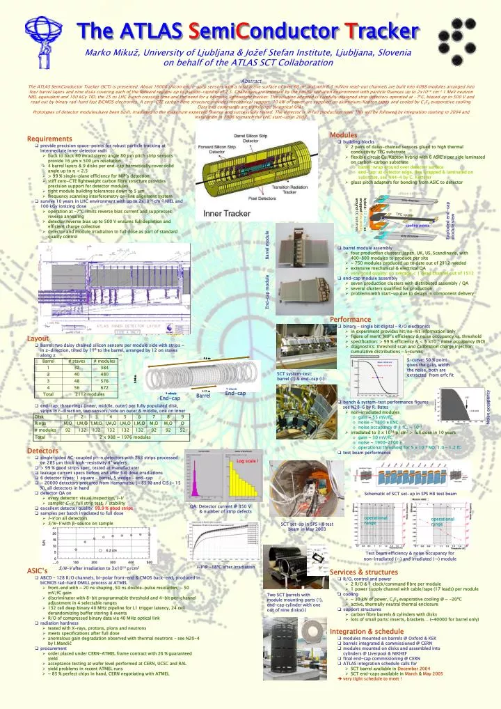
strip direction strip direction End-cap Barrel End-cap Log scale ! The ATLAS SemiConductorTracker Marko Mikuž, University of Ljubljana & Jožef Stefan Institute, Ljubljana, Slovenia on behalf of the ATLAS SCT Collaboration Abstract The ATLAS SemiConductor Tracker (SCT) is presented. About 16000 silicon micro-strip sensors with a total active surface of over 60 m2 and with 6.3 million read-out channels are built into 4088 modules arranged into four barrel layers and nine disks covering each of the forward regions up to pseudo-rapidity of 2.5. Challenges are imposed by the hostile radiation environment with particle fluences up to 2x1014 cm-2 1 MeV neutron NIEL equivalent and 100 kGy TID, the 25 ns LHC bunch crossing time and the need for a hermetic lightweight tracker. The solution adopted is carefully designed strip detectors operated at -7oC, biased up to 500 V and read out by binary rad-hard fast BiCMOS electronics. A zero-CTE carbon fibre structure provides mechanical support. 30 kW of power are supplied on aluminium/Kapton tapes and cooled by C3F8 evaporative cooling. Data and commands are transferred by optical links. Prototypes of detector modules have been built, irradiated to the maximum expected fluence and successfully tested. The detector is in full production now. This will be followed by integration starting in 2004 and installation in 2006 to match the LHC start-up in 2007. • Modules • building blocks • 2 pairs of daisy-chained sensors glued to high thermal conductivity TPG substrate • flexible circuit Cu/Kapton hybrid with 6 ASIC’s per side laminated on carbon-carbon substrate • barrel: wrap around over detector surface • end-cap: at detector edge, flex wrapped & laminated on substrate, see N44-4 by C. Ketterer • glass pitch adapters for bonding from ASIC to detector • barrel module assembly • four production clusters: Japan, UK, US, Scandinavia, with 400-800 modules to produce per site • ~ 750 modules produced up to date out of 2112 needed • extensive mechanical & electrical QA • very good quality: on average < 1 dead channel out of 1512 • end-cap module assembly • seven production clusters with distributed assembly / QA • several clusters qualified for production • problems with start-up due to delays in component delivery • Requirements • provide precision space-points for robust particle tracking at intermediate inner detector radii • back to back 40 mrad stereo angle 80 µm pitch strip sensors provide 16 µm x 500 µm resolution • 4 barrel layers & 9 disks per end-cap hermetically cover solid angle up to η < 2.5 • > 99 % single-plane efficiency for MIP’s detection • stiff zero-CTE lightweight carbon fibre structure provides precision support for detector modules • tight module building tolerances down to 5 µm • frequency scanning interferometry on-line alignment system • survive 10 years in LHC environment with up to 2x1014 cm-2 NIEL and 100 kGy ionizing dose • operation at -7ºC limits reverse bias current and suppresses reverse annealing • detector reverse bias up to 500 V ensures full depletion and efficient charge collection • detector and module irradiation to full dose as part of standard quality control silicon sensors hybrid: 12 ASIC’s on wrapped flex circuit around CC substrate TPG spine Exploded end-cap module view cooling points pitch adapter Barrel module End-cap module • Performance • binary – single bit digital – R/O electronics • in experiment provides hit/no-hit information only • figure of merit: MIP’s efficiency & noise occupancy vs. threshold • specification: > 99 % efficiency & < 5 x10⁻⁴ noise occupancy (NO) • diagnostics: threshold scan and calibration charge injection: cumulative distributions – S-curves • bench & system-test performance figures see N28-6 by R. Bates • non-irradiated modules • gain ~ 55 mV/fC • noise ~ 1500 e ENC • noise occupancy @ 1 fC: ~ 10-5 • irradiated to 3 x 10¹⁴ p/cm2 > full dose in 10 years • gain ~ 30 mV/fC • noise ~ 1900-2100 e • operational threshold for 5 x 10⁻⁴ NO: 1.0 – 1.2 fC • test beam performance • Layout • barrel: two daisy chained silicon sensors per module side with strips ~ in z-direction, tilted by 11º to the barrel, arranged by 12 on staves along z • end-cap: three rings (inner, middle, outer) per fully populated disk, strips in r-direction, two sensors/side on outer & middle, one on inner S-curve: 50 % point gives the gain, width the noise, both are extracted from erfc fit SCT system-test: barrel (↑) & end-cap (↓) Noise occupancy • Detectors • single-sided AC-coupled p+-n detectors with 768 strips processed on 285 µm thick high-resistivity 4” wafers • > 99 % good strips spec, tested at manufacturer • leakage current specs before and after full dose irradiations • 6 detector types: 1 square – barrel, 5 wedge – end-cap • ~ 20000 detectors procured from Hamamatsu (~ 85 %) and CiS (~ 15 %), all detectors in hand • detector QA on • every detector: visual inspection, I-V • sample: C-V, full strip test, I stability • excellent detector quality: 99.9 % good strips • samples per batch irradiated to full dose • I-V on all detectors • S/N-V with β-source on sample Schematic of SCT set-up in SPS H8 test beam QA: Detector current @ 350 V & number of strip defects operational range operational range SCT set-up in SPS H8 test beam in May 2003 Test beam efficiency & noise occupancy for non-irradiated (←) and irradiated (→)module I-V @ -18ºC after irradiation S/N-V after irradiation to 3x10¹⁴ p/cm2 • ASIC’s • ABCD – 128 R/O channels, bi-polar front-end & CMOS back-end, produced in biCMOS rad-hard DMILL process at ATMEL • front-end with ~ 20 ns shaping, 50 ns double-pulse resolution, ~ 50 mV/fC gain • discriminator with 8-bit programmable threshold and 4-bit per-channel adjustment in 4 selectable ranges • 132 cell deep binary 40 MHz pipeline for L1 trigger latency, 24 cell derandomizing buffer storing 8 events • R/O of compressed binary data via 40 MHz optical link • radiation hardness • tested with X-rays, protons, pions and neutrons • meets specifications after full dose • anomalous gain degradation observed with thermal neutrons – see N20-4 by I.Mandić • procurement • order placed under CERN-ATMEL frame contract with 26 % guaranteed yield • acceptance testing at wafer level performed at CERN, UCSC and RAL • yield problems in recent ATMEL runs • ~ 85 % perfect chips in hand, CERN negotiating with ATMEL • Services & structures • R/O, control and power • 2 R/O & 1 clock/command fibre per module • 1 power supply channel with cable/tape (17 leads) per module • cooling • ~ 30 kW of power, C3F8 evaporative cooling @ ~ -20ºC • active, thermally neutral thermal enclosure • support structures • carbon fibre barrels & cylinders with disks • lots of small parts: inserts, brackets… (~40000 for barrel only) Two SCT barrels with module mounting parts (↑), end-cap cylinder with one out of nine disks(↓) • Integration & schedule • modules mounted on barrels @ Oxford & KEK • barrels integrated & commissioned @ CERN • modules mounted on disks and assembled into cylinders @ Liverpool & NIKHEF • final end-cap commissioning @ CERN • ATLAS integration schedule calls for • SCT barrel available in December 2004 • SCT end-caps available in March & May 2005 • very tight schedule to meet !