Download
1 / 13
140 likes | 361 Views
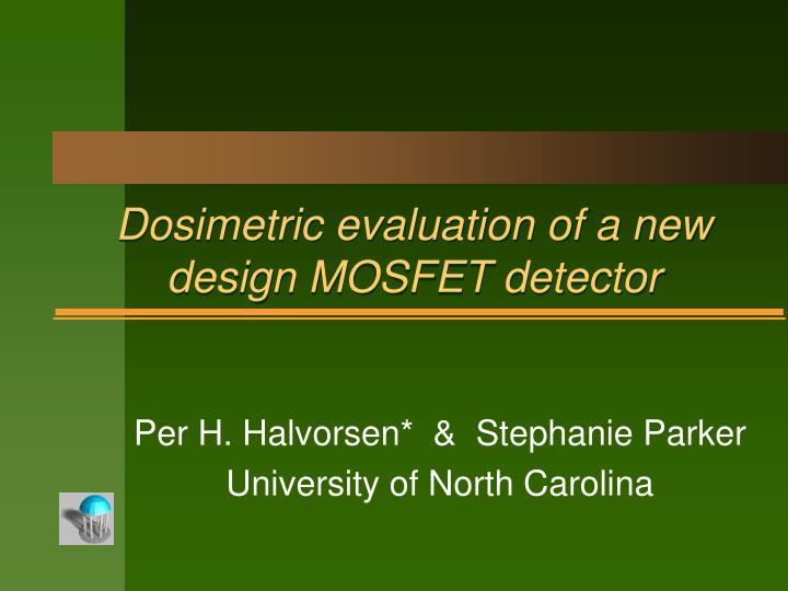
Dosimetric evaluation of a new design MOSFET detector. Per H. Halvorsen* & Stephanie Parker University of North Carolina. Introduction. Other authors 1-4 have noted the following characteristics of the Thomson&Nielsen MOSFET detectors (TN-RD-502 detectors with TN-RD-50 dosimetry system)

E N D
Dosimetric evaluation of a newdesign MOSFET detector Per H. Halvorsen* & Stephanie Parker University of North Carolina
Introduction Other authors 1-4 have noted the following characteristics of the Thomson&Nielsen MOSFET detectors (TN-RD-502 detectors with TN-RD-50 dosimetry system) Small modality dependence (< 5%) Small energy dependence (< 5%). { At very low energies (e.g. 33KeV), a pronounced over-response is evident; its magnitude (factor of 4.2) is greater than TLD (1.2) but less than diodes (7.7). } High reproducibility (< 3%) No angular dependence for electron beams Very small angular dependence for photon beams at angles of 135, but an over-response beyond these angles, reaching a maximum of approximately 18% and 13% at 180 to the normal, for 6MV and 18MV photon beams respectively. 2
Introduction cont. The manufacturer (Thomson&Nielsen) has recently introduced a redesigned MOSFET detector, called the “Isotropic MOSFET”. When used with the TN-RD-50 dosimetry system, the manufacturer claims a significant reduction in the photon anisotropy described above. We have measured the dosimetric characteristics of this new detector, and compared the characteristics with those of the current design (TN-RD-502). Initially, the detectors’ energy dependence and inherent buildup were evaluated, to ensure that the beneficial aspects of the current design have not been compromised in order to reduce the anisotropy. Next, a series of measurements were conducted to evaluate the angular dependence of the new design. The same measurements were performed for the current design, and the results compared. 3
Energy & modality dependence For a 100 cGy irradiation at the calibration condition (10x10 field, isocenter at depth 5.0 cm for photons, dmax with 100 SSD for electrons), we obtained the following signal (in mV) with the new MOSFETs: + 3% 15 E 295 21 E 6 X 290 Average 12 E 18 X 285 10 E 6 E 8 E - 3% Our measured calibration factors show a total range of 3.6% for all energies and both modalities; an average value would give a ±2% uncertainty, nearly identical to that of the current design. Repeated measurements with different detectors have shown a ±1.5% level of reproducibility. 4
Reproducibility For a 100 cGy irradiation at the calibration condition (10x10 field, isocenter at depth 5.0 cm for photons), we obtained the following signal (in mV) with the new MOSFETs, using a high-sensitivity bias: + 2% 295 290 Average 285 - 2% ---- Std MOSFET ---- New MOSFET These measurements (repeated with different detectors) show a ±1.5% level of reproducibility, consistent with the current design detectors and high-sensitivity bias. 5
Inherent buildup As a reference, the buildup characteristics of our Primus accelerator’s 6 and 18 MV photon beams were measured with an Exradin A-11 parallel-plate ionization chamber, in a virtual-water phantom. Measurements were made with the following thicknesses of virtual water above the detector: 0.0, 0.2, 0.3, 0.5, 0.7, 1.0, 1.5, and 5.0. The effective depth of measurement (proximal electrode surface, at 0.05 g/cm2 depth) was accounted for when plotting the buildup curve, and a curve-fit was used to extrapolate to depth 0.00 cm. Our calibration geometry for the MOSFET detectors is identical to that used for the dose calibration of the accelerator (at isocenter, depth 5.0 cm, 10*10 cm field). All readings were, therefore, expressed as a percentage of the dose at the calibration condition. 6
6MV photon Buildup ---- P-P chamber ---- Std MOSFET ---- New MOSFET Depth dose 100 80 60 40 Dose 20 Depth 0.1 0.5 1.5 3.5 5.0 7
18MV photon Buildup ---- P-P chamber ---- Std MOSFET ---- New MOSFET Depth dose 100 80 60 40 Dose 20 Depth 0.1 0.5 1.5 3.5 5.0 8
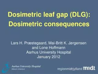
Angular dependence The MOSFET detectors were placed, flat side “up”, in a virtual water phantom with a 0.5 cm thick sheet of bolus material under the detector. This eliminated the slight air-gap which would otherwise result from placing the detector directly between two slabs of virtual water. The detectors were placed such that the depth to the center of the detector was 5.0 cm from the front, side and rear. Both detector designs were irradiated in this geometry. The detectors were irradiated with a fixed field size and distance (detector at isocenter), and at angles of 0°, 90 ° and 180 ° relative to the normal to the detector’s flat surface. For an intermediate, 45 ° measurement, the measured dose was normalized back to 5.0 cm depth by the measured isocentric fractional dose (TRR). Sample data are shown below. 9
6MV photon: Angular dependence - results 1.20 1.15 Dangle/Dnormal 1.10 1.05 1.00 0.95 Angle relative to normal 0° 45° 90° 180° ---- Standard MOSFET ---- New MOSFET 10
18MV photon: Angular dependence - results 1.20 1.15 Dangle/Dnormal 1.10 1.05 1.00 0.95 Angle relative to normal 0° 45° 90° 180° ---- Standard MOSFET ---- New MOSFET 11
Conclusion Our evaluations have confirmed the findings of other investigators regarding the standard MOSFET detector system (see page 2). Our analysis of the new detector design shows no change in many important characteristics (energy & field size dependence, reproducibility). We have found the new MOSFET detector design to have an angular dependence of 3% or less over the full 360° range. With this detector redesign, resulting in minimal angular dependence, we conclude that this system is a reliable and efficient in-vivo dosimetry system, and well suited for quality assurance in our IMRT program. 12
References 1. Ramani, R., et.al., “Clinical dosimetry using MOSFETs”, Int J Radiat Oncol Biol Phys 1997 Mar:37(4), 959-964. 2. Francsescon, P., et.al., “Use of a new type of radiochromic film, a new parallel-plate micro-chamber, MOSFETs, and TLD800 microcubes in the dosimetry of small beams”, Med Phys 1998 25(4), 503-511. 3. Edwards, C.R., et.al., “The response of a MOSFET, p-type semiconductor and LiF TLD to quasi-monoenergetic X-Rays”, Phys Med Biol 1997 42(12), 2383-2391. 4. Scalchi, P., and Francescon, P., “Calibration of a MOSFET detection system for 6MV in-vivo dosimetry”, Int J Radiat Oncol Biol Phys 1998 Mar:40(4), 987-993. 13