Download
1 / 25
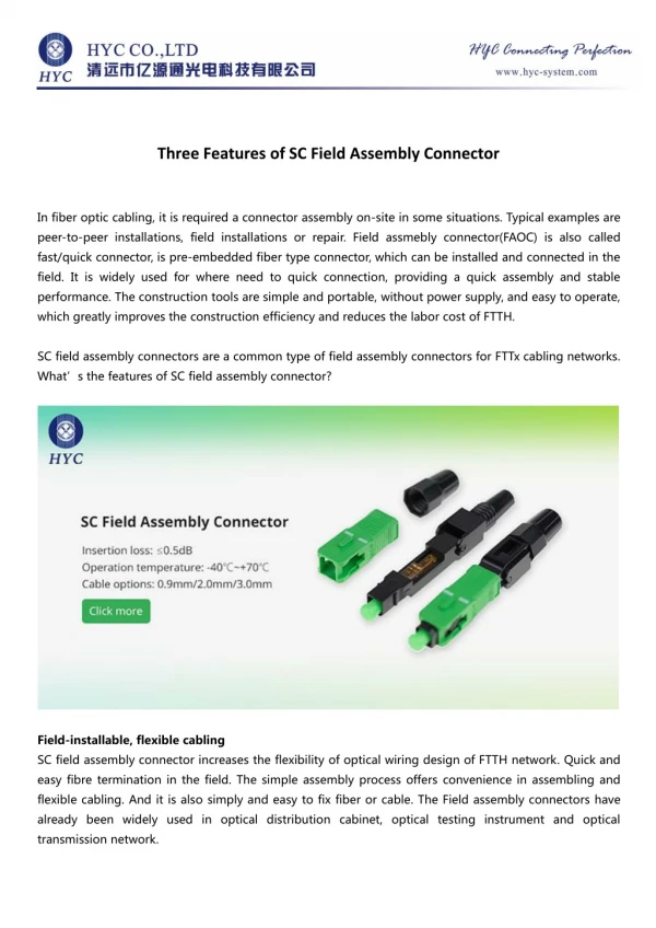
270 likes | 428 Views
IT3-32mm SI Report Three-Piece Mezzanine Connector for 20+ Gbps Applications. October 29, 2009. Outline. What is IT3 HFSS simulation models for connector and via Insertion and return losses, NEXT, FEXT, and impedance profile Insertion loss to crosstalk ratio (ICR)

E N D
IT3-32mm SI Report Three-Piece Mezzanine Connectorfor 20+ Gbps Applications October 29, 2009
Outline • What is IT3 • HFSS simulation models for connector and via • Insertion and return losses, NEXT, FEXT, and impedance profile • Insertion loss to crosstalk ratio (ICR) • Fully populated vs. 50% density • Connector-only vs. full channel • Eye diagrams • Summary • Appendix • Measurement vs. simulation correlation • Measured ICR for IT3-25mm
Mating receptacle IT3D-***S-BGA(**) Mating side Mating / unmating Interposer Signal Ground Interposer assembly Mounting side Installed and locked Signal / Ground configuration Locking latch Mounting receptacle IT3M-***S-BGA(**) What is IT3 • Proven 3-piece design for improved electrical performance and mechanical reliability
Differential pairs 12 15 11 13 14 10 6 8 9 7 2 4 1 3 5 Signal pin Ground pin HFSS simulation model • A .s60p file was created, and the differential pair’s response was examined. Only a quadrant of model is shown.
Via model • A .s60p Touchstone file was also created to study the effect of via stub and coupling.
IEEE 802.3ap channel spec. • IEEE 802.3ap defined the channel spec. of insertion-loss-to-crosstalk ratio (ICR) up to 5 GHz for 10 Gbps data rate. We will extrapolate this ICR curve to 10 GHz for 20 Gbps data rate. 10 GHz (for 20 Gbps)
Insertion loss ICR wrt. FEXT: Board B Board A FEXT Board B ICR wrt. NEXT: Insertion loss Board A Connector and via transition is assumed to be at approximately the middle of channel. NEXT Connector’s ICR • The connector and via transition’s contribution to ICR is independent of channel length, because the insertion loss and crosstalk attenuate at the same rate.
Impedance and delay @1 GHz IT3-32mm connector-only response(Fully populated) • All insertion and return losses, and NEXT and FEXT are shown.
IT3-32mm connector-only response(60% density) • Both NEXT and FEXT are reduced, if some pins are skipped (i.e., terminated or assigned to low-speed signals).
IT3-32mm connector-only response(50% density) • Even less NEXT and FEXT with 50% density.
Impedance @60ps rise time (20% to 80%) • IT3’s receptacles were designed to have slightly high impedance to offset the via’s and via stub’s low impedance. Connector only Connector + ~60mil via stubs
6” IT3 120 mil FR408 6” 60 mil stub Via model 20 Gbps FEXT for via-connector-via (w/o trace attenuation) ICR with 14 FEXTs ICR in a full channel(Fully populated) • ICR with 14-aggressor connector and via FEXT, and ~60 mil stub meets the extrapolated IEEE 802.3ap spec. for 20 Gbps.
6” IT3 120 mil FR408 6” 60 mil stub Via model 20 Gbps FEXT for via-connector-via (w/o trace attenuation) ICR with 6 FEXTs ICR in a full channel(50% density) • ICR with 6-aggressor connector and via FEXT, and ~60 mil stub gives plenty of margin @20 Gbps, as compared to the extrapolated IEEE 802.3ap spec.
6” IT3 120 mil FR408 6” 60 mil stub Via model Channel simulation @6.25 Gbps(Fully populated) • ADS simulation with 3-tap TX equalization gives good open eyes @6.25 Gbps with ~60mil via stub and 14 FEXT included. Without connector Jitter = 15.06ps Eye Height = 987.57mV With connector and 14 FEXT Jitter = 18.57ps Eye Height = 866.27mV
6” IT3 120 mil FR408 6” 60 mil stub Via model Channel simulation @12.5 Gbps(50% density) • ADS simulation with 3-tap TX equalization gives good open eyes @12.5 Gbps with ~60mil via stub and 6 FEXT included. Without connector Jitter = 12.44ps Eye Height = 579.12mV With connector and 6 FEXT Jitter = 18.48ps Eye Height = 469.88mV
6” IT3 120 mil FR408 6” 60 mil stub Via model Channel simulation @20 Gbps(50% density) • ADS simulation with 7-tap TX equalization gives good open eyes @20 Gbps with ~60mil via stub and 6 FEXT included. Without connector Jitter = 12.89ps Eye Height = 320.58mV With connector and 6 FEXT Jitter = 19.39ps* Eye Height = 194.93mV* *Degradation is mainly due to via stubs.
Summary • IT3 meets the extrapolated IEEE802.3ap’s ICR spec. for 20+ Gbps. • Both characterization and demo boards are available for evaluation.
Appendix A Measurement vs. simulation correlation
Top test board Bottom test board - - = Connector + Test Boards Bottom Test Board Top Test Board Connector Only Measurement Setup • To measure the connector’s performance directly, we pre-characterized and de-embedded the test boards.
Insertion and return losses • Good correlation in differential insertion and return losses.
NEXT • Good correlation in differential NEXT.
FEXT • Good correlation in differential FEXT.
Appendix B Measured ICR for IT3-25mm
Test board • VNA measurements were taken on 120mil test boards with IT3-25mm connector, 2 via transitions, and 6”+6” PCB traces routed through the middle layers. * The ICR curves in the following slides will also be valid for other trace length.
W U R N L J G E C A 13 Victim pair 15 “Skipped” pins 17 Optimized 60% density for 20 Gbps • IT3 meets ICR spec. (with FEXT) for 20 Gbps if 40% pins are “skipped”. ICR wrt. NEXT* ICR wrt. FEXT* * These curves include 8 aggressors for one IT3-25mm connector and two via transitions. The skipped pins are terminated in this case.