Download
1 / 127
1.27k likes | 1.51k Views
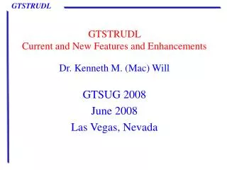
GTSTRUDL Upcoming Version 32 Release and Future Enhancements. Dr. Kenneth M.(Mac) Will GTSUG 2011 June 2011 Delray Beach, Florida. Presentation Outline. Status of Version 32 New Features in Version 32 Future Enhancements. Status of Version 32. Beta testing scheduled for August.

E N D
GTSTRUDL Upcoming Version 32 ReleaseandFuture Enhancements Dr. Kenneth M.(Mac) Will GTSUG 2011 June 2011 Delray Beach, Florida
Presentation Outline • Status of Version 32 • New Features in Version 32 • Future Enhancements
Status of Version 32 • Beta testing scheduled for August. • Documentation is in progress. • Plan to ship in October.
DBX • WRITE CODE CHECK RESULTS has been added. This DBX file contains the same data as found in the output from LIST CODE CHECK RESULTS. ASCII80 and BINARY sequential formats are supported.
DBX • Syntax: WRITE CODE (CHECK) (RESULTS) -(MEMBERS list) Examples: • WRITE CODE ALL MEMBERS • WRITE CODE RES MEMBERS EXISTING - 1 TO 1000
DBX • The WRITE CABLE FORCES command has been added to the DBX feature. This DBX file contains the normal stress, the corresponding normal force, and the three global element nodal reaction components at each node for all active static loadings. All documented file formats and access modes are supported.
DBX (cont) • Syntax: WRITE CABLE FORCES (MEMBERS list) Examples: • WRITE CABLE FORCES ALL MEMBERS • WRITE CABLE FORCES MEMBERS EXISTING - 1 TO 1000
Dynamics • The GT64MLANCZOS eigenvalue analysis solution method has been implemented, extending high-performance sparse-equation eigenvalue analysis to 64-bit computer platforms.
Dynamics (cont) • GT64MLANCZOS is the most powerful version of the GTLANCZOS family of eigenvalue analysis solution methods (GTLANCZOS, GTSELANCZOS, and now GT64MLANCZOS) presently available in GTSTRUDL and incorporates the following features:
Dynamics (cont) • The Lanczos iteration process employs an in-core, single processor version of the GT64M sparse equation solver. Multiple processors and out-of-core processing are not available in this initial implementation for Version 32.
Dynamics (cont) • All computations associated with the Lanczos iteration process take advantage of 64-bit addressing on 64-bit platforms, greatly increasing the number of degrees of freedom that can be treated and the number of modes that can be computed when compared to the GTLANCZOS and GTSELANCZOS methods. There is also a modest increase of solution speed when compared to the GTSELANCZOS method, but this becomes less apparent as the number of modes increases.
Dynamics (cont) • The GT64MLANCZOS method is activated when the GT64M option is specified by the ACTIVE SOLVER command: ACTIVE SOLVER GT64M or when the GT64MLANCZOS method is specified in the EIGENSOLUTION PARAMETERS command: EIGENSOLUTION PARAMETERS SOLVE USING GT64MLANCZOS
Dynamics (cont) • Example of problem run using GT64MLANCZOS which could not be executed using 32 bit eigensolvers: Dynamic DOF = 329,994 Number of Modes = 300 Total time to solve = 1,693 sec Total time to check solution = 182 sec Virtual memory used = appx. 6 GB
Dynamics (cont) • Modest efficiency and performance improvements have been made to the GTSES Lanczos eigenvalue analysis procedure (GTSELANCZOS). However, GTSELANCZOS remains a single-processor, 32-bit solver governed by 32-bit virtual memory allocation and addressing limitations.
Finite Elements • A new eight node solid element with incompatible modes will be available (IPSLIM). This element will offer substantially improved accuracy over the existing eight node solid element for structures with bending and shear deformation. The element will include all of the features currently available with the current eight node solid (IPSL) element.
Finite Elements (cont) • A new four node plane stress quadrilateral with three dof (including drilling dof) will be added – Q6CDRL • A new four node moderately thick plate bending element will be added – PBMITC • A new four node moderately thick plate element (stretching and bending) with 6 dof will be added - SBMITC = Q6CDRL + PBMITC
General (cont) • PRINT MEMBER LENGTH SORTED LIMIT v now prints the total number of members that meet the specified limit after the list of member lengths. This only applies to LIMITS with decimal numbers, which indicates a length value and where the number of members meeting the criterion is unknown, and not to LIMITS with an integer number, which indicates a specified number of member lengths to print.
General (continued) Example: { 4367} > UNITS CM { 4368} > PRINT MEMBER LENGTH SORTED LIMIT 20.0 (output omitted) **** INFO_PRTMBL - Found 10 members < 20.000
General (continued) • A new option has been added to the PRINT command, PRINT MEMBER BETA ANGLES, which allows you to print only BETA angles, without the other CONSTANTS. The command syntax and a few examples are shown on the next slide.
General (continued) • Syntax: Examples: PRINT MEMBER BETA ANGLES NONZERO ONLY - TOLERANCE 0.1 DEGREES PRINT MEMBER BETA GROUPED COMMAND -FORMAT
General (continued) • A GLOBAL option has been added to LIST FORCES. This option will print member forces in the global reference frame, instead of the standard local (member) reference frame. • Syntax: LIST FORCES (GLOBAL)
General (continued) • Two new options have been added to the LIST JOINT FORCES command: GLOBAL (WITH TOTAL) and MEMBERS m_list. The GLOBAL option causes the member and element forces to be rotated from the local coordinate system to the global coordinate system.
General (continued) In the case of members with ECCENTRICITIES, the forces are transformed from the flexible end of the member to the joint - therefore LIST JOINT FORCES GLOBAL will not match LIST FORCES even after resolving the coordinate systems for members with ECCENTRICITIES.
General (continued) The WITH TOTAL option will print the summation of all listed members and elements for each DOF for each joint and active load. The GLOBAL option always outputs all six global DOF, instead of being restricted to member DOF. The MEMBERS m_listoption restricts the printed forces to members or elements in m_list.
General (continued) • Syntax of the modified command:
General (continued) • { 191} > LIST JOINT FORCES GLOBAL JOINT 3 • ----------------------------------------------------------------------------------------------------------------------------------- • --- Loading - 1 • ----------------------------------------------------------------------------------------------------------------------------------- • GLOBAL joint forces output by loading • MEMBER/ REF • /-JOINT-/-ELEMENT-/-FRAME-/---------------------FORCES---------------------/---------------------MOMENTS-------------------/--ECC-/ • FORCE X FORCE Y FORCE Z MOMENT X MOMENT Y MOMENT Z • 3 1 GLOBAL 6.119 6.148 0.000 0.000 0.000 11.185 NO • 3 2 GLOBAL 6.119 6.148 0.000 0.000 0.000 -11.185 NO • 3 3 GLOBAL -6.119 -6.148 0.000 0.000 0.000 11.476 NO • 3 4 GLOBAL -6.119 -6.148 0.000 0.000 0.000 -11.476 NO
General (continued) • { 193} > LIST JOINT FORCES GLOBAL WITH TOTAL JOINT 3 MEMBERS 1 2 • ----------------------------------------------------------------------------------------------------------------------------------- • --- Loading - 1 • ----------------------------------------------------------------------------------------------------------------------------------- • GLOBAL joint forces output by loading • MEMBER/ REF • /-JOINT-/-ELEMENT-/-FRAME-/---------------------FORCES---------------------/---------------------MOMENTS-------------------/--ECC-/ • FORCE X FORCE Y FORCE Z MOMENT X MOMENT Y MOMENT Z • 3 1 GLOBAL 6.119 6.148 0.000 0.000 0.000 11.185 NO • 3 2 GLOBAL 6.119 6.148 0.000 0.000 0.000 -11.185 NO • --------------- --------------- --------------- --------------- --------------- --------------- • Totals 12.237 12.295 0.000 0.000 0.000 0.000
General (continued) • The RENAME command has been added. This command allows you to change the name of an existing component - joint, member/element, load or group. Syntax: RENAME type old_name new_name where type is the type of component to rename. The allowable types are: JOINT (or NODE), MEMBER (or ELEMENT), LOAD, GROUP.
General (continued) • The MEMBER PROPERTIES Command has been enhanced giving the user the ability to define member properties for Channels and Polygonal Tubes by specifying their dimensions. The following are examples of the two new options for the MEMBER PROPERTIES Command:
General (continued) MEMBER PROPERTIES 1 TO 10 CHANNEL TOTAL DEPTH 16.97 - WEB THICKNESS 0.585 FLANGE WIDTH 10.425 - FLANGE THICKNESS 0.985 11 TO 20 POLYGONAL TUBE - DIAMETER BETWEEN FLATS 14.35 - NUMBER OF SIDES 8 - THICKNESS 0.985
General (continued) Members whose properties have been defined through these options can be code checked by the GTSTRUDL Codes that support such cross-sections. Also, these new options are available for prismatic and variable members.
General (continued) • The CALCULATE SOIL SPRINGS command has been enhanced to: 1) Allow a single KS value without an element list, which indicates that GTSTRUDL should find all elements and element faces that lie on the specified plane and create an assumed element list. This makes adding soil springs to an entire slab on one level much simpler.
General (continued) 2) Added a NO SUPPORT CHECK option to the COMPRESSION ONLY nonlinear springs capability. NLS elements will be added to the model without regard to the current support status of the involved joints as opposed to the current requirement that soil springs can be added only to joints with the appropriate DOF (FX, FY or FZ) restrained. This allows you greater flexibility in modeling, but leaves the responsibility of creating a stable analysis model up to you. An informational message is generated if the NO SUPPORT CHECK option is used, but the appropriate DOF is fixed - which will result in the created NLS being nonfunctional:
General (continued) 3) The name of the generated NLS has been added to the output if the COMPRESSION ONLY option is used. In addition, the informative comments output below the spring value report now reflect the actual names of the generated NLS so they can be copied from the output to be added to your input or pasted into the Command window.
General (continued) • A new command will be implemented to make it easier for the user to specify the Beta angle for members with eccentricities in planes which are not parallel to a global plane. The new command is • ACTIVE BETA ANGLE DEFINITION - With JOINT TO JOINT OR ECCENTRIC option
GTMenu • Member loads on cable elements can now be displayed. • The Inquire dialog no longer disappears when the Graphics window is activated.
GTMenu (cont) • Force Diagrams and value labels can now be rotated according to the Beta Angles on Members. A FY Diagram is plotted in the local xy plane by default; a FZ Diagram is plotted in the local xz plane by default; a MY Diagram is plotted in the local xz plane by default; and a MZ Diagram is plotted in the local xy plane by default
GTMenu (cont) • The GENERATE INPUT FILE feature now includes NONLINEAR EFFECTS, NONLINEAR SPRING PROPERTIES and NONLINEAR SPRING ELEMENT commands. In addition, OBJECT commands are included along with group titles . • "TYPE RMS" and "TYPE ABS" Load Combinations are now translated and put into the input file.
GTMenu (cont) • Finite elements are now labeled closer to their centroid. • When checking for duplicate joints, the duplicate joints, members, or elements are now labeled on the screen. • When checking for floating joints, the floating joints are now labeled on the screen.
GTMenu (cont) • Redraw solid will display the nine Unistrut sections in the GTSTRUDL Unistrut table as shown on the next slides.
GTMenu (cont) • A new option has been added to allow you to create Section Property Groups when you are creating new members. The new option to the Member Properties dialog is shown
GTMenu (cont) • When Refining a Finite Element Mesh and changing to a higher order element, the mapping shown on the next slide is now followed which shows the lower order element and the new higher order element.
GTMenu (cont) • The following eight cases are used in the mapping: (1) a plane stress triangle maps to type 'LST' (2) a plane stress quad maps to type 'IPQQ' (3) a plate bending triangle produces an error saying unavailable (4) a plate bending quad maps to type 'IPBQQ' (5) a tridimensional 6 node prism maps to type 'WEDGE15' (6) a tridimensional 8 node brick maps to type 'IPSQ' (7) a plate triangle produces an error saying unavailable (8) a plate quad produces an error saying unavailable.
GTMenu (cont) • A graphical interface to the LIST SUM FORCES command has been implemented. This works by starting with a line or plane of joints that cut the structure. (A line cuts a 2-D structure whereas a plane is necessary to specify a cut of a 3-D structure.) Next, all members and elements above or below the cut are marked. Then individual members or elements can be deselected. Finally the forces are summed for this specification, producing textual output.
GTMenu (cont) cut results