Download
1 / 102
1.03k likes | 1.15k Views
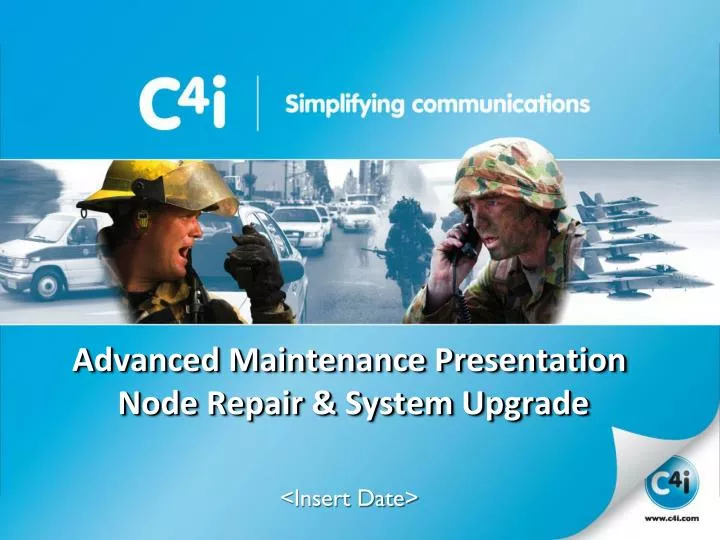
Advanced Maintenance Presentation Node Repair & System Upgrade. <Insert Date>. Advanced Maintenance Presentation Node Repair & System Upgrade. 1. Agenda. Advanced Maintenance Presentation 1. Agenda. Topics covered in this training presentation are: Agenda Purpose

E N D
Advanced Maintenance Presentation Node Repair & System Upgrade <Insert Date>
Advanced Maintenance Presentation Node Repair & System Upgrade 1. Agenda
Advanced Maintenance Presentation1. Agenda • Topics covered in this training presentation are: • Agenda • Purpose • Addresses the intended audience • Typical System Overview (Basic) • Before The Upgrade • Configuration to Remember • OIU configuration • RIU configuration • CSU configuration (telephony) • Dial Plan • CM configuration Doc: 1322-019 Ver: 1.0
Advanced Maintenance Presentation1. Agenda • Network to be wary of… • Network Structure and impact of incorrect configuration • IP Switch configurations • IP Plan • Multicast addresses • Upgrading Spare Part or System (software roll-out) • Operator Position • Operator Console Unit (OCU) • Operator Interface Unit (OIU) • Radio Interface Unit (RIU) • DSP/AIM • Linux ETX • Communication Server Unit (CSU) Doc: 1322-019 Ver: 1.0
Advanced Maintenance Presentation Node Repair & System Upgrade 2. Purpose
Advanced Maintenance Presentation2. Purpose • This training course is directed to personnel that are responsible for maintaining the SwitchplusIP™ Voice Communications System. • Prerequisites • Students have participated in the following C4i training courses: • System Maintenance Training Course (Mandatory) • Configuration Module Training Course (Mandatory) • Operator Position Training Course (Optional) Doc: 1322-019 Ver: 1.0
Advanced Maintenance Presentation2. Purpose • Students will learn • Typical System Architecture • Customer specific configuration and where it resides • How to capture configuration customisations • Upgrading Spare Parts and the system as a whole (software roll-out) Doc: 1322-019 Ver: 1.0
Advanced Maintenance Presentation Node Repair & System Upgrade 3. Typical System (Overview)
Advanced Maintenance Presentation3. Typical System (Overview) • The SwitchplusIP™ Voice Communication System provides operators the ability to interface with radio, telephone and intercom services. • The system is comprised of the following basic components: • Operator Positions • Communication Server Units (CSU) • Radio Interface Units (RIU) • The system is monitored and managed by the Maintenance Server Unit (MSU) • The basic system components are interconnected via Ethernet and managed by dual redundant (optional) LAN Interface Units (a.k.a. IP Switches). Doc: 1322-019 Ver: 1.0
Advanced Maintenance Presentation3. Typical System (Overview) • The SwitchplusIP™ Network Topologies (Overview) • Single (non-redundant) LAN • This model is usually reserved for small systems such as a mobile dismount system where down-time is not a critical factor. • Dual Redundant LAN • C4i preferred network configuration prior to Product 7.0 • All equipment is connected to two (2) independent LANs (i.e. LAN A and LAN B) where all data is duplicated on each LAN. • Active-Standby LAN (a.k.a. Main / Backup) • C4i preferred network configuration post Product 7.0 • All equipment is connected to two (2) LANs (i.e. LAN A and LAN B) however data is not duplicated on both LANs; instead LAN A is used unless the connection fails then reverting to LAN B (or standby connection). Doc: 1322-019 Ver: 1.0
Advanced Maintenance Presentation3. Typical System (Overview) • Single (non-redundant) LAN • In a Single LAN topology, all equipment is connected to a single LAN, as the name suggests. • Should any piece of equipment’s connection to the LAN fail (such as an OIU, RIU or CSU), its resources are lost as there is no other network communication path for the unit. • Therefore if an OIU loses its Ethernet connection (such as the port is blocked at the switch or the cable is disconnected or broken), that operator position is lost. • For an RIU, its radio resources are lost. • For a CSU, if the system only contains one CSU, all radio and telephony services are lost; however, if the system contains two CSUs, the secondary CSU will manage radio and telephony resource connections. Doc: 1322-019 Ver: 1.0
Advanced Maintenance Presentation3. Typical System (Overview) • Single (non-redundant) LAN • It is recommended that if a Single LAN topology is used, a very high availability IP switch is used to minimize the likeliness of a switch port failing. Note: If the switch completely fails, all services are lost. Doc: 1322-019 Ver: 1.0
Advanced Maintenance Presentation3. Typical System (Overview) • Single (non-redundant) LAN Doc: 1322-019 Ver: 1.0
Advanced Maintenance Presentation3. Typical System (Overview) • Dual Redundant LAN • All equipment is connected to two (2) independent LANs (i.e. LAN A and LAN B). • Data is sent on both LAN A and LAN B. • In this situation, should any piece of equipment’s connection to LAN A fail, its resources are not lost as it will still have a network connection on LAN B. Note: In order to maintain a dual-redundant topology between remote locations or additional sites (for multi-site systems), two communication links must be used and two switches are required at each location or site. A single communication link can be used to connect the locations or sites using routers but this will make the routers and link a single point of failure. Doc: 1322-019 Ver: 1.0
Advanced Maintenance Presentation3. Typical System (Overview) • Dual Redundant LAN Doc: 1322-019 Ver: 1.0
Advanced Maintenance Presentation3. Typical System (Overview) • Active-Standby LAN • All equipment is connected to two (2) LANs (i.e. LAN A and LAN B). • Data is not duplicated on both LANs, instead LAN A is used unless the connection fails then reverting to LAN B (or standby connection). • In this situation, should any piece of equipment’s connection to a switch fail, its resources are not lost as it will still have a network connection. Audio may be lost temporarily as the equipment switches from using LAN A to LAN B. The impact is minimal. Note that in order to maintain a dual-redundant topology between remote locations or additional sites (for multi-site systems), two communication links must be used and two switches are required at each location or site. A single communication link can used to connect the locations or sites using routers but this will make the routers and link a single point of failure. Doc: 1322-019 Ver: 1.0
Advanced Maintenance Presentation3. Typical System (Overview) • Active-Standby LAN Doc: 1322-019 Ver: 1.0
Advanced Maintenance Presentation3. Typical System (Overview) • Communication across a WAN • SwitchPlusIP™ has the ability to access radios at the same site and across multiple sites using a communication link or WAN. • If resources other than the SwitchPlusIP™ system use the link care must be taken to ensure system stability. • The following points must be considered: • Bandwidth – Varies with system size, usage, recording methodology and network topology. • IP Plan – Devices that are not part of the SwitchPlusIP™ system can not share the same IP addresses or use the same multicast ports. • Network Isolation – Need to verify that devices outside the system are blocked from writing to or monitoring anything on the IP Plan. Doc: 1322-019 Ver: 1.0
Advanced Maintenance Presentation3. Typical System (Overview) • Network Isolation • If resources other than the SwitchPlusIP™ system use the same network infrastructure measures may need to be put in place to ensure system stability and harmony. • Virtual LAN • VLANs provide network segmentation by treating VLAN members as through they are on a separate physical network. • They provide data security through this network segmentation (or isolation). • They can span across WANs allowing physically separate sites appear as local. • Simplify traffic flow management across shared networks. Doc: 1322-019 Ver: 1.0
Advanced Maintenance Presentation3. Typical System (Overview) Notes: ------------------------------------------------------------------------------------------------------------- ------------------------------------------------------------------------------------------------------------- ------------------------------------------------------------------------------------------------------------- ------------------------------------------------------------------------------------------------------------- ------------------------------------------------------------------------------------------------------------- ------------------------------------------------------------------------------------------------------------- ------------------------------------------------------------------------------------------------------------- ------------------------------------------------------------------------------------------------------------- ------------------------------------------------------------------------------------------------------------- Doc: 1322-019 Ver: 1.0
Advanced Maintenance Presentation Node Repair & System Upgrade 4. Before The Upgrade
Advanced Maintenance Presentation4. Before The Upgrade • There are a couple of important things to remember before performing a node replacement or software node/system upgrade. • Configuration. • What needs to be captured before commencing a part replacement or upgrade? • What has to be reinstated after the upgrade? • Network configuration to be wary of… Doc: 1322-019 Ver: 1.0
Advanced Maintenance Presentation4. Before The Upgrade • Configuration NOT ALL SYSTEM PARAMETERS ARE STORED WITHIN THE CONFIGURATION MODULE Doc: 1322-019 Ver: 1.0
Advanced Maintenance Presentation4. Before The Upgrade • System Integration specific configuration parameters • After installing the SwitchplusIP™ Product site specific configuration customisations are normally performed as no two sites are identical. • These customisations reside on the specific nodes of the system. • OIU configuration • RIU configuration • CSU configuration • and then there is the CM Configuration (or Configuration Module file) Doc: 1322-019 Ver: 1.0
Advanced Maintenance Presentation4. Before The Upgrade • Operator Position Configuration • There is no specific OCU configuration that requires backing up however the OIU may be a different story if using a mixture of different types or kinds of peripherals. • Each of the OIUs interfaces (headset, handset, desk microphones, etc) have setup parameters like: • Mic & Ear gain and bias voltage (for electret microphones) Doc: 1322-019 Ver: 1.0
Advanced Maintenance Presentation4. Before The Upgrade • Operator Position Configuration • You may wish to record the OIU Name Doc: 1322-019 Ver: 1.0
Advanced Maintenance Presentation4. Before The Upgrade • Operator Position Configuration • Network Configuration (Dual Redundant / Bridged / Active-Standby) • Record the LAN Options. NOTE: Bridged mode in a LAN A/B environment will have dire consequences. Doc: 1322-019 Ver: 1.0
Advanced Maintenance Presentation4. Before The Upgrade • Operator Position Configuration • Unfortunately there is not an automated method for capturing these parameters and then applying them to the system post upgrade. • There is however a method for rolling-out these configuration parameters to all OIU's simultaneously after capturing them manally… • The Product Release Disc • Generic OIU Parameters (for all OIUs) reside: • \DSP_Software\Command_Post_S11\OIU\AimOIUConfig.txt • Specific OIU Parameters (for individual OIUs) reside: • \DSP_Software\Command_Post_S11\OIU\OIU1-AimOIUConfig.txt • \DSP_Software\Command_Post_S11\OIU\OIU2-AimOIUConfig.txt • \DSP_Software\Command_Post_S11\OIU\OIU3-AimOIUConfig.txt Doc: 1322-019 Ver: 1.0
Advanced Maintenance Presentation4. Before The Upgrade • Radio Interface Unit (DSP/AIM) Configuration • The Software Release Disc will contain generic configuration parameters for each radio interface. Therefore any radio specific modifications made during the system integration phase need to be captured. • These parameters include: • Radio Tx and Rx Signalling (E&M, 4-Wire, DIO, VAD/VOX, etc) • VAD Threshold and hold timers • Gain Settings • Serial Port Settings for radio control, etc Doc: 1322-019 Ver: 1.0
Advanced Maintenance Presentation4. Before The Upgrade • Radio Interface Unit (DSP/AIM) Configuration • The recommended method for capturing these parameters (for your records) is via the RIU web page. Specifically the CONFIG SUMMARY page. Doc: 1322-019 Ver: 1.0
Advanced Maintenance Presentation4. Before The Upgrade • Radio Interface Unit (DSP/AIM) Configuration • Print a copy of this page for each RIU within the system. Doc: 1322-019 Ver: 1.0
Advanced Maintenance Presentation4. Before The Upgrade • Radio Interface Unit (DSP/AIM) Configuration Doc: 1322-019 Ver: 1.0
Advanced Maintenance Presentation4. Before The Upgrade • Radio Interface Unit (DSP/AIM) Configuration • Using this information the RIUs can be manually updated (via the web page) post upgrade or the RIU specific configuration files can be edited for automatic roll-out during the software upgrade. • The Product Release Disc • Generic RIU Parameters (for all RIUs) reside: • \DSP_Software\Command_Post_S11\RIU\AimOIUConfig.txt • Specific RIU Parameters (for individual RIUs) reside: • \DSP_Software\Command_Post_S11\RIU\RIU1-AimRIUConfig.txt • \DSP_Software\Command_Post_S11\RIU\RIU2-AimRIUConfig.txt • \DSP_Software\Command_Post_S11\RIU\RIU3-AimRIUConfig.txt Doc: 1322-019 Ver: 1.0
Advanced Maintenance Presentation4. Before The Upgrade • CSU Configuration • The Event Log is not preserved through a software installation event. • To Archive Event Logs go into the CSU web page selecting Maintenance Scripts Login. • Username: manager • Password: manager Doc: 1322-019 Ver: 1.0
Advanced Maintenance Presentation4. Before The Upgrade • CSU Configuration • Use the Sync DB if replacing spare in Dual CSU system. This will ensure Logs are synchronised between both CSUs (prevents loss in the case of fail-over event). • Use the Start Archive or Start Backup when upgrading to new software release. Doc: 1322-019 Ver: 1.0
Advanced Maintenance Presentation4. Before The Upgrade • CSU Configuration • Standard CSU configuration for SwitchplusIP™ Product is P/N 685-800-006 • Telephony Interface configuration of 8 Port FXO (analogue) and 2 Port E1/T1 (Digital) as depicted below. • Telephony configuration other than standard Product must be reconfigured as part of the software upgrade activity. Doc: 1322-019 Ver: 1.0
Advanced Maintenance Presentation4. Before The Upgrade • CSU Configuration • Telephony hardware configuration is stored on the CSU and must be retrieved using an (S)FTP or secure copy (SCP) client such as WinSCP • Connect to the CSU and login with superuser privileges. Doc: 1322-019 Ver: 1.0
Advanced Maintenance Presentation4. Before The Upgrade • CSU Configuration • Traverse to directory • /etc/asterisk • Drag file chan_dahdi.conf to temp drive or a memory key. Doc: 1322-019 Ver: 1.0
Advanced Maintenance Presentation4. Before The Upgrade • CSU Configuration • Select Copy • The file is then copied to the local computer. Doc: 1322-019 Ver: 1.0
Advanced Maintenance Presentation4. Before The Upgrade • CSU Configuration • Sample chan_dahdi.conf information • E1 port signalling and protocol information. • FXO port configuration Doc: 1322-019 Ver: 1.0
Advanced Maintenance Presentation4. Before The Upgrade • CSU Configuration • Project specific dial plan changes must also be preserved if different from standard Product configuration (most likely). • These are also stored on the CSU and retrieved in the same manner as the telephony hardware configuration. • Extensions.conf [/etc/asterisk/extensions.conf] • This configuration file contains the dial plan and controls how all incoming and outgoing calls are routed within the system. • This file may be different between software Product releases and therefore may require manual massaging. • SIP.conf [/etc/asterisk/sip.conf] • This configuration file contains parameters relating to sip client access. All SIP clients hosts must be configured within this file to gain access to the system. For example this is where the Operator Position, Radio and SIP Trunks contexts are identified. Doc: 1322-019 Ver: 1.0
Advanced Maintenance Presentation4. Before The Upgrade • User Accounts & Phonebook • All user accounts (with the exception of the C4iMaintainer account) are managed centrally on the CSU by the Lightweight Directory Access Protocol (LDAP) service. • All phonebook entries are also managed by LDAP. • These can be exported from LDAP using the web interface or LDAPAdmin tool. Doc: 1322-019 Ver: 1.0
Advanced Maintenance Presentation4. Before The Upgrade • User Accounts • Start LDAPAdmin • Select Start->Connection… • Select New connection • Enter Host IP Address • Select Fetch DNs • Select OK Doc: 1322-019 Ver: 1.0
Advanced Maintenance Presentation4. Before The Upgrade • User Accounts • Select CSU Connection • Select OK Doc: 1322-019 Ver: 1.0
Advanced Maintenance Presentation4. Before The Upgrade • User Accounts • You can export: • Whole database • Accounts • Groups • People (i.e. Phonebook) • Select Whole database • Select Tools->Export Doc: 1322-019 Ver: 1.0
Advanced Maintenance Presentation4. Before The Upgrade • User Accounts • Enter in a filename or use the folder icon to browse your local computer. • Check include subdirectories • Select OK • Select CLOSE once complete Doc: 1322-019 Ver: 1.0
Advanced Maintenance Presentation4. Before The Upgrade • User Accounts • All account information is stored in plain text (including passwords) so handle exported files accordingly. • Importing user accounts and the phonebook are just as simple by selecting the Tools->Import Option Doc: 1322-019 Ver: 1.0
Advanced Maintenance Presentation4. Before The Upgrade • CM Configuration • Last but not least the CM configuration must be backed up. CAUTION CM Configuration files may be incompatible between SwitchplusIP™ Product Releases. Professional conversion may be required that can only be performed by C4i. Doc: 1322-019 Ver: 1.0
Advanced Maintenance Presentation4. Before The Upgrade • Network configuration to be wary of… • Network Structure and impact of incorrect configuration • If the current network is setup in an Active-Standby configuration, installing a node (such as an RIU or OIU) in the Dual Redundant (LAN A / LAN B) or Bridged configuration will not have any drastic affects on the system however that specific node will not behave as expected; However • If the current network is setup in a Dual Redundant (LAN A / LAN B) configuration, installing a node (such as an RIU or OIU) in the Bridged configuration will cause unwanted network loops. This may cause the entire system to fail. • IP Switch configurations • Correct protocols must be setup depending on network topology (e.g. Spanning tree protocol, LANs, etc). Doc: 1322-019 Ver: 1.0
Advanced Maintenance Presentation4. Before The Upgrade • Network configuration to be wary of… • IP Plan • Release 7.0 changed the standard IP plan for Product. • Multicast address range • 238.1.1.1 database notifier • 239.0.0.0 – 239.255.255.255 SwitchplusIP™ Voice multicast allocation • Time Server Architecture • CSU manages system time • CSU points to external time source Doc: 1322-019 Ver: 1.0