Download
1 / 30
300 likes | 578 Views
MCQUAY DIGITAL SCROLL SYSTEM. Installation. INSTALLATION. Bad Installation – System will not operate as per design Waste of Money Waste of Time Bad Image. 3 Major Categories Unit Installation Piping Installation Wiring Installation. INSTALLATION. Unit Installation Indoor Unit

E N D
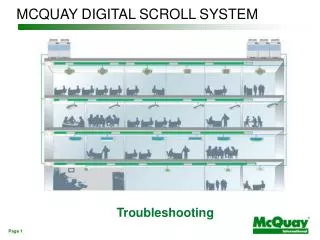
MCQUAY DIGITAL SCROLL SYSTEM Installation
INSTALLATION • Bad Installation – System will not operate as per design • Waste of Money • Waste of Time • Bad Image • 3 Major Categories • Unit Installation • Piping Installation • Wiring Installation
INSTALLATION • Unit Installation • Indoor Unit • Outdoor Unit Note: Installation of indoor unit is same as normal direct expansion unit.
INSTALLATION • Outdoor Unit Installation • Sufficient area around the unit. No barrier for supply air and discharge air. • Avoid discharge air return to the unit (Hot Air short-circuiting) • Strong foundation for the unit
INSTALLATION Handling Outdoor Unit Correct
INSTALLATION Handling Outdoor Unit Wrong
INSTALLATION Correct Wrong
INSTALLATION Outdoor Unit Spacing (Single Outdoor Unit) Wall / Barrier higher than unit Wall / Barrier lower than unit Side View
INSTALLATION Outdoor Unit Spacing (Single Outdoor Unit) Top View (Barrier higher than unit)
INSTALLATION Outdoor Unit Spacing (Single Outdoor Unit) Top View (Barrier lower than unit)
INSTALLATION Outdoor Unit Spacing (More than 1 unit) Top View (Wall / Barrier restriction same as 1 outdoor unit)
INSTALLATION Outdoor Unit Spacing (More than 1 unit) Top View (Wall / Barrier restriction same as 1 outdoor unit)
INSTALLATION Outdoor Unit Spacing (More than 1 unit) Top View (Wall / Barrier restriction same as 1 outdoor unit)
INSTALLATION • Outdoor Unit Foundation • Floor location strength • Able to withstand the unit weight and vibration • Layout for drainage, piping & cables • Different level, avoid blocking. • Important for MDS260~300B(BR). Oil balancing pipe must be lower than the connection joint • Screw bolt required to further tighten the unit • Avoid the unit from falling due to earthquake
INSTALLATION • Piping Installation • Ensure piping is dry, clean and no air leakage
INSTALLATION • Piping Installation • Refnet & distributor joints to be install horizontally
INSTALLATION • Piping Installation • Refnet & distributor joints to be install horizontally
INSTALLATION • Piping Installation • EXV box to be install vertically
INSTALLATION • Piping Installation • Insulation • Able to withstand the pipe heat • Heatpump Unit – heat resistance polyethylene foamed ( > 120 Deg C) • Cooling only - Polyethylene ( > 100 Deg C) • Insulation method • Thickness of insulation
INSTALLATION Insulation Method Wrong Method Correct Method
INSTALLATION • Thickness of insulation • Depends on pipe diameter • Notes: • Hot and wet environment, increase then thickness of the insulation • Cooling with ambient less than 10 deg C, recommended to insulate the liquid pipe.
CONTROL Communication • Twisted Pair wired with shielding (20AWG) • Shield wire to be earth on 1 end of the network • Connected serially to the adjacent unit (Daisy Chain Connection) • Same polarity between units
CONTROL Communication For the last indoor, Jumper JP-7 need to be shorted (Top left Corner of the indoor board) System Wiring
CONTROL Communication System Wiring Ain = Terminal 30 Bin = Terminal 31 APC = Terminal 32 BPC = Terminal 33
B A CONTROL Communication MDS080~240 Outdoor PCB Indoor PCB
CONTROL Communication For the last indoor, Jumper JP-7 need to be shorted (Top left Corner of the indoor board) System Wiring - MDS260~300B(BR)
CONTROL Communication MDS260/280/300 + MDS120/150BRM MDS130/150BRS Indoor Units
CONTROL Control & Monitoring Software RS485 Gateway RS232 1. Review indoor unit status and error history 2. Monitor and control all indoor unit 3. Weekly timer and holiday timer setting Computer Indoor units Outdoor units Centralize Control