Download
1 / 61
620 likes | 798 Views
NETE0510 Frame Relay. Dr. Supakorn Kungpisdan supakorn@mut.ac.th. Outline. Background Frame Relay Virtual Circuits Frame Relay Bandwidth and Flow Control LAPF Frame Format Inverse ARP Non-broadcast Multi-access. Background.

E N D
NETE0510Frame Relay Dr. Supakorn Kungpisdan supakorn@mut.ac.th NETE0510: Communication Media and Data Communications
Outline • Background • Frame Relay • Virtual Circuits • Frame Relay Bandwidth and Flow Control • LAPF Frame Format • Inverse ARP • Non-broadcast Multi-access NETE0510: Communication Media and Data Communications
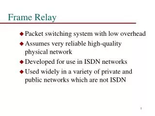
Background • The most technical innovation to come out of standardization work on narrowband ISDN is Frame Relay. • Frame relay is a streamlined technique for packet switching that operates at the data link layer with much less overhead than packet switching X.25 NETE0510: Communication Media and Data Communications
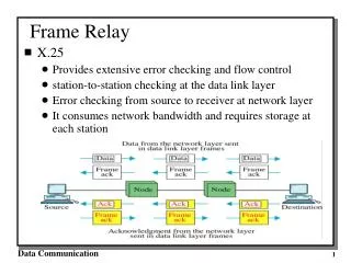
Key features of the X.25 • Call-control packets, used for setting up and clearing virtual circuits, are carried on the same channel and same virtual circuit as data packets. In effect, inband signaling is used. • Multiplexing of virtual circuits takes place at layer 3 • Both layer 2 and layer 3 include flow-control and error-control mechanisms NETE0510: Communication Media and Data Communications
Problems of X.25 • Packet switching results in considerable overhead. For a simple network of just three nodes between source and destination • Source data needs to be stored for possible retransmission • X.25 header is added to blocks of data to form a packet • Routing calculations are made • Packets enclosed in an LAPB frame by adding LAPB header and trailer • At intermediate node, flow- and error-control are performed • The node removes data link layer field for routing purposes • The entire process is repeated at each hop across the network NETE0510: Communication Media and Data Communications
Problems of X.25 (cont’d) 2 3 5 6 1 4 • With highly reliable digital transmission technology, e.g. one used in ISDN, with a low probability of error, the above approach is not the best. • Moreover, such overheads degrade effective utilization of the links NETE0510: Communication Media and Data Communications
Background (cont’d) • Frame relay eliminates overhead of X.25 by having these characteristics: • Call control signaling is carried on a separate logical connection from user data. Thus, intermediate nodes need not maintain state tables or process messages relating to call control on an individual per-connection basis. • Multiplexing and switching of logical connections are in layer 2. • Eliminate one entire layer of processing • There is no hop-to-hop flow- and error-control (performed at a higher layer) NETE0510: Communication Media and Data Communications
Frame relay operation A single-user data frame is sent from source to destination, and an acknowledgement, generated at a higher layer, is carried back in a frame NETE0510: Communication Media and Data Communications
Background (cont’d) • Advantage of frame relay is streamlining the communication process. • Protocol functionality required at user-network interface and internal network processing are reduced. • Thus, lower delay and higher throughput can be expected. • Disadvantages of frame relay compared to X.25: • Lost the ability to do link-by-link flow and error control. • In X.25 multiple VCs are carried on a single physical link and LAPB is available at link layer for providing reliable transmission. • However, with the increasing reliability of transmission and switching facilities, this is not a major disadvantage NETE0510: Communication Media and Data Communications
Outline • Background • Frame Relay • Virtual Circuits • Frame Relay Bandwidth and Flow Control • LAPF Frame Format • Inverse ARP • Non-broadcast Multi-access NETE0510: Communication Media and Data Communications
Frame Relay • Frame Relay is a packet-switched, connection-oriented, WAN service. It operates at the data link layer of the OSI reference model. • Uses a subset of the high-level data-link control (HDLC) protocol called Link Access Procedure for Frame Relay (LAPF). • Frames carry data between user devices called DTE, and DCEat the edge of the WAN. • Originally designed to allow ISDN equipment to have access to a packet-switched service on a B channel. However, Frame Relay is now a stand-alone technology. NETE0510: Communication Media and Data Communications
Frame Relay Operation NETE0510: Communication Media and Data Communications
Frame Relay (cont’d) • Frame Relay is often used to interconnect LANs. • When this is the case, a router on each LAN will be the DTE. • A serial connection, such as a T1/E1 leased line, will connect the router to a Frame Relay switch of the carrier at the nearest point-of-presence for the carrier. • The Frame Relay switch is a DCE device. • Frames from one DTE will be moved across the network and delivered to other DTEs by way of DCEs. NETE0510: Communication Media and Data Communications
Frame Relay Switches NETE0510: Communication Media and Data Communications
Frame Relay Concepts NETE0510: Communication Media and Data Communications
Outline • Background • Frame Relay • Virtual Circuits • Frame Relay Bandwidth and Flow Control • LAPF Frame Format • Inverse ARP • Non-broadcast Multi-access NETE0510: Communication Media and Data Communications
Virtual Circuits • The connection through the Frame Relay network between two DTEs is called a virtual circuit (VC). • Two types of VCs: • Switched virtual circuits (SVCs): VCs that are established dynamically by sending signaling messages to the network. • Permanent virtual circuits (PVCs):preconfigured by the carrier are used. • A VC is created by storing input-port to output-port mapping in the memory of each switch and thus linking one switch to another until a continuous path from one end of the circuit to the other is identified. NETE0510: Communication Media and Data Communications
Virtual Circuits (cont’d) NETE0510: Communication Media and Data Communications
Virtual Circuits NETE0510: Communication Media and Data Communications
Local Significance of DLCIs The data-link connection identifier (DLCI) is stored in the Address field of every frame transmitted. NETE0510: Communication Media and Data Communications
Frame Relay Stack Layered Support NETE0510: Communication Media and Data Communications
Outline • Background • Frame Relay • Virtual Circuits • Frame Relay Bandwidth and Flow Control • LAPF Frame Format • Inverse ARP • Non-broadcast Multi-access NETE0510: Communication Media and Data Communications
Frame Relay Bandwidth and Flow Control • Usually there are several PVCs operating on the access link with each VC having dedicated bandwidth availability. This is called the committed information rate (CIR). • The CIR is the rate at which the service provider agrees to accept bits on each VC. CIR may be less than port speed • Sum of CIRs may be greater than port speed. Statistical multiplexing accommodates the bursty nature of computer communications since channels are unlikely to be at their maximum data rate simultaneously. • The difference between the CIR and the maximum, whether the maximum is port speed or lower (that the switch can handle), is called the Excess Information Rate (EIR). • Switch can accept the frames at the rate CIR+EIR • The time interval over which the rates are calculated is called the committed time (Tc). • The number of committed bits in Tc is the committed burst (Bc) • The extra number of bits above the committed burst, up to the maximum speed of the access link, is the excess burst (Be). NETE0510: Communication Media and Data Communications
Frame Relay Bandwidth and Flow Control (cont’d) • Although the switch accepts frames in excess of the CIR, each excess frame is marked at the switch by setting the Discard Eligible (DE)bit to "1" in the address field. • The switch maintains a bit counter for each VC. An incoming frame is marked DE if it puts the counter over Bc. • An incoming frame is discarded if it pushes the counter over Bc + Be. • At the end of each Tc seconds the counter is reset. The counter may not be negative, so idle time cannot be saved up. NETE0510: Communication Media and Data Communications
Frame Relay Bandwidth and Flow Control (cont’d) • Frames arriving at a switch are queued or buffered prior to forwarding. • It is possible that there will be an excessive buildup of frames at a switch. This causes delays. • Delays lead to unnecessary retransmissions that occur when higher-level protocols receive no acknowledgment within a set time. • This can cause a serious drop in network throughput. • To avoid this problem, Frame Relay switches incorporate a policy of dropping frames from a queue to keep the queues short. • Frames with their DE bit set will be dropped first. NETE0510: Communication Media and Data Communications
Frame Relay Bandwidth and Flow Control (cont’d) • When a switch sees its queue increasing, it tries to reduce the flow of frames to it. • It does this by notifying DTEs of the problem by setting the Explicit Congestion Notification (ECN)bits in the frame address field. • The Forward ECN (FECN)bit is set on every frame that the switch receives on the congested link. • The Backward ECN (BECN)bit is set on every frame that the switch places onto the congested link. • DTEs receiving frames with the ECN bits set are expected to try to reduce the flow of frames until the congestion clears. • The DE, FECN and BECN bits are part of the address field in the LAPF frame. NETE0510: Communication Media and Data Communications
Frame Relay Bandwidth and Flow Control (cont’d) Queue NETE0510: Communication Media and Data Communications
Frame Relay Bandwidth and Flow Control (cont’d) NETE0510: Communication Media and Data Communications
Frame Relay Bandwidth and Flow Control (cont’d) NETE0510: Communication Media and Data Communications
Frame Relay Address Mapping and topology • WANs are often interconnected as a star topology. A central site hosts the primary services and is connected to each of the remote sites needing access to the services NETE0510: Communication Media and Data Communications
Frame Relay Address Mapping and topology (cont’d) • In a hub and spoke topology the location of the hub is chosen to give the lowest leased line cost. • When implementing a star topology with Frame Relay, each remote site has an access link to the frame relay cloud with a single VC. • The hub has an access link with multiple VCs, one for each remote site. • Because Frame Relay tariffs are not distance related, the hub does not need to be in the geographical center of the network. NETE0510: Communication Media and Data Communications
Frame Relay Address Mapping and topology (cont’d) Hub NETE0510: Communication Media and Data Communications
Frame Relay Address Mapping and topology • For large networks, full mesh topology is seldom affordable. This is because the number of links required for a full mesh topology grows at almost the square of the number of sites. • While there is no equipment issue for Frame Relay, there is a limit of less than 1000 VCs per link. • In practice, the limit will be less than that, and larger networks will generally be partial mesh topology. • With partial mesh, there are more interconnections than required for a star arrangement, but not as many as for a full mesh. The actual pattern is very dependant on the data flow requirements. NETE0510: Communication Media and Data Communications
Frame Relay Address Mapping and topology (cont’d) NETE0510: Communication Media and Data Communications
Frame Relay Address Mapping and topology NETE0510: Communication Media and Data Communications
Outline • Background • Frame Relay • Virtual Circuits • Frame Relay Bandwidth and Flow Control • LAPF Frame Format • Inverse ARP • Non-broadcast Multi-access NETE0510: Communication Media and Data Communications
LAPF Frame Format EAExtended Address field signifies up to two additional bytes in the Frame Relay header, thus greatly expanding the number of possible addresses. NETE0510: Communication Media and Data Communications
LAPF Frame – Address Field 6-bits EA 4-bits NETE0510: Communication Media and Data Communications
Data Link Control Identifier • The 10-bit DLCI associates the frame with its virtual circuit • It is of local significance only - a frame will not generally be delivered with the same DLCI with which it started • Some DLCI’s are reserved (Consolidated Link Layer Management) NETE0510: Communication Media and Data Communications
Consolidated Link Layer Management • It may occur that there are no frames traveling back to the source node which is causing the congestion. • In this case, the network will want to send its own message to the problematic source node. • The standard, however, does not allow the network to send its own frames with the DLCI of the desired virtual circuit. • To address this problem, ANSI defined the Consolidated Link Layer Management (CLLM). • The ANSI standard (T1.618) defines the format of the CLLM message. It contains a code for the cause of the congestion and a listing of all DLCIs that should act to reduce their data transmission to lower congestion. NETE0510: Communication Media and Data Communications
Local Management Interface (LMI) • Each DLCI corresponds to a PVC. • It is sometimes necessary to transmit information about this connection (e.g., whether the interface is still active) the valid DLCIs for the interface and the status of each PVC. • This information is transmitted using the reserved DLCI 1023 (ANSI, ITU) or DLCI 0 (Cisco), depending on the standard used. NETE0510: Communication Media and Data Communications
LMI (cont’d) • There are several LMI types, each of which is incompatible with the others. • The LMI type configured on the router must match the type used by the service provider. • Three types of LMIs are supported by Cisco routers: • Cisco — The original LMI extensions • Ansi — Corresponding to the ANSI standard T1.617 Annex D • q933a — Corresponding to the ITU standard Q933 Annex A • LMI messages are carried in a variant of LAPF frames. This variant includes four extra fields in the header so that they will be compatible with the LAPD frames used in ISDN. • Control, protocol discriminator, call reference, LMI message type • The address field carries one of the reserved DLCIs. NETE0510: Communication Media and Data Communications
LMI Frame Format Contains DLCI 1 2 1 1 1 1 2 1 Flag Address Control PD CR MT LMI Message FCS Flag NETE0510: Communication Media and Data Communications
Outline • Background • Frame Relay • Virtual Circuits • Frame Relay Bandwidth and Flow Control • LAPF Frame Format • Inverse ARP • Non-broadcast Multi-access NETE0510: Communication Media and Data Communications
Inverse ARP • If the router needs to map the VCs to network layer addresses, it will send an Inverse ARP message on each VC. • The Inverse ARP message includes the network layer address of the router, so the remote DTE, or router, can also perform the mapping. • The Inverse ARP reply allows the router to make the necessary mapping entries in its address to DLCI map table. • If several network layer protocols are supported on the link, Inverse ARP messages will be sent for each. NETE0510: Communication Media and Data Communications
Stages of Inverse ARP andLMI Operation #1 NETE0510: Communication Media and Data Communications
Stages of Inverse ARP and LMI Operation #2 NETE0510: Communication Media and Data Communications
Configuring Basic Frame Relay The bandwidth value is used by IGRP, EIGRP, and OSPFto determine the metric of the link. NETE0510: Communication Media and Data Communications
Configuring a Static Frame Relay Map • The local DLCI must be statically mapped to the network layer address of the remote router when the remote router does not support Inverse ARP. • This is also true when broadcast traffic and multicast traffic over the PVC must be controlled. These static Frame Relay map entries are referred to as static maps. NETE0510: Communication Media and Data Communications
Configuring a Static Frame Relay Map (cont’d) NETE0510: Communication Media and Data Communications