Download

1 / 12

E N D
Copyrighted material licensed to Saipem. No further reproduction or distribution permitted. Printed / viewed by: [mohammad.hosseini@saipem.com] @ 2017-03-14 COPYRIGHT NOTICE & TERMS OF USE This document is the copyright of the Publisher. All rights reserved. The contract allowing you to use this document contains the following terms of use which must be followed:- (a) You may view and print a single copy of a document contained in the Subscription for reference purposes only and only for internal purposes within the site on which such copies are made, providing such copies are dated and destroyed after the reference usage, typically no more than 60 working days after use, subject to the exception described in clause (b) below. Such copies may not be filed to form part of any hard copy reference collection. (b) Where you have a specification or tender requirement to reproduce a document or portions of a document as part of its documentation for external submission in response to a tender, the necessary pages of the document, including the whole document if required, may be reproduced and submitted provided a copyright notice is included. You shall notify SAI Global of any such use. For internal and archival purposes only, a paper copy may be attached to your documentation and shall be considered a permanent part of that documentation. (c) Under no circumstances are you permitted to reproduce all or part of any document for external use or for use in any other site or group of sites, except as set forth in (b) above. (d) You may not remove any proprietary markings or electronic watermarks, including any copyrights and trademarks. (e) You may copy a maximum of 25% of the content of a document within the Subscription and paste it to another document for internal use. The copied content in the new document must contain a copyright notice “Copyright [name of publisher] Date where date is the date of copyrighted material. Such content is licensed for use only for the duration of the relevant Subscription. (f) For ISO standards, the material is reproduced from ISO publications under International Organization for Standardization (ISO) Copyright License number SAI GLOBAL/MCEA/2008. Not for resale. No part of these ISO publications may be reproduced in any form, electronic retrieval system or otherwise, except as allowed under the copyright law in the country of use, or with the prior written consent of ISO (Case postale 56, 1211 Geneva 20, Switzerland, email: copyright@iso.org) or ISO’s Members. SAI GLOBAL, Index House, Ascot, Berks, SL5 7EU, UK : +44 (0)1344 636300. Fax: +44 (0)1344 291194. E-mail: standards@saiglobal.com. www.ili.co.uk SAI GLOBAL, Forest Road Office Centre, 210 Route 4 East, Paramus, NJ 07652, USA 201-986-1131. Fax: 201-986-7886. E-mail: sales@ili-info.com. www.ili-info.com SAI GLOBAL, 286 Sussex Street, Sydney NSW 2000, Australia : +61 2 8206 6060. Fax: +61 2 8206 6019. E-mail: sales@saiglobal.com. www.saiglobal.com
Copyrighted material licensed to Saipem. No further reproduction or distribution permitted. Printed / viewed by: [mohammad.hosseini@saipem.com] @ 2017-03-14 Designation: G217 − 16 Standard Guide for Corrosion Monitoring in Laboratories and Plants with Coupled Multielectrode Array Sensor Method1 This standard is issued under the fixed designation G217; the number immediately following the designation indicates the year of original adoption or, in the case of revision, the year of last revision. A number in parentheses indicates the year of last reapproval. A superscript epsilon (´) indicates an editorial change since the last revision or reapproval. 1. Scope 1.1 This guide outlines the procedure for conducting corro- sion monitoring in laboratories and plants by use of the coupled multielectrode array sensor (CMAS) technique. 1.2 For plant applications, this technique can be used to assess the instantaneous non-uniform corrosion rate, including localized corrosion rate, on a continuous basis, without re- moval of the monitoring probes, from the plant. 1.3 For laboratory applications, this technique can be used to study the effects of various testing conditions and inhibitors on non-uniform corrosion, including pitting corrosion and crevice corrosion. 1.4 Units—The values stated in SI units are to be regarded as the standard. No other units of measurement are included in this standard. 1.5 This standard does not purport to address all of the safety concerns, if any, associated with its use. It is the responsibility of the user of this standard to establish appro- priate safety and health practices and determine the applica- bility of regulatory limitations prior to use. tance of Stainless Steels and Related Alloys by Use of Ferric Chloride Solution G96 Guide for Online Monitoring of Corrosion in Plant Equipment (Electrical and Electrochemical Methods) G102 Practice for Calculation of Corrosion Rates and Re- lated Information from Electrochemical Measurements G193 Terminology and Acronyms Relating to Corrosion G199 Guide for Electrochemical Noise Measurement 3. Terminology 3.1 Definitions—The terminology used herein, if not spe- cifically defined otherwise, shall be in accordance with Termi- nology G193. Definitions provided herein and not given in Terminology G193 are limited only to this guide. 3.2 Definitions of Terms Specific to This Standard: 3.2.1 coupled multielectrode n—device with multiple working electrodes that are coupled through an external circuit such that all the electrodes operate at the same electrode potential to simulate the electrochemical behavior of a single-piece metal. 3.2.2 non-uniform corrosion, n—corrosion that occurs at various rates across the metal surface, with some locations exhibiting higher anodic rates while others have higher ca- thodic rates, thereby requiring that the electron transfer occurs between these sites within the metal. 3.2.2.1 Discussion—Non-uniform corrosion includes both localized corrosion and uneven general corrosion (1).3Non- uniform corrosion also includes the type of general corrosion that produces even surfaces at the end of a large time interval, but uneven surfaces during small time intervals. 3.2.3 uneven general corrosion, n—corrosion that occurs over the whole exposed surface or a large area at different rates. 3.2.3.1 Discussion—In this guide, general corrosion is fur- ther divided into even general corrosion, or uniform corrosion, which is defined as the corrosion that proceeds at exactly the same rate over the surface of a material (see Terminology G193) and uneven general corrosion. Uneven general corro- sion is defined as the general corrosion that produces uneven array sensor, CMAS, 2. Referenced Documents 2.1 ASTM Standards:2 G1 Practice for Preparing, Cleaning, and Evaluating Corro- sion Test Specimens G4 Guide for Conducting Corrosion Tests in Field Applica- tions G16 Guide for Applying Statistics to Analysis of Corrosion Data G46 Guide for Examination and Evaluation of Pitting Cor- rosion G48 Test Methods for Pitting and Crevice Corrosion Resis- 1This guide is under the jurisdiction of ASTM Committee G01 on Corrosion of Metals and is the direct responsibility of Subcommittee G01.11 on Electrochemical Measurements in Corrosion Testing. Current edition approved Nov. 1, 2016. Published November 2016. DOI: 10.1520/G0217-16. 2For referenced ASTM standards, visit the ASTM website, www.astm.org, or contact ASTM Customer Service at service@astm.org. For Annual Book of ASTM Standards volume information, refer to the standard’s Document Summary page on the ASTM website. 3The boldface numbers in parentheses refer to a list of references at the end of this standard. Copyright © ASTM International, 100 Barr Harbor Drive, PO Box C700, West Conshohocken, PA 19428-2959. United States 1
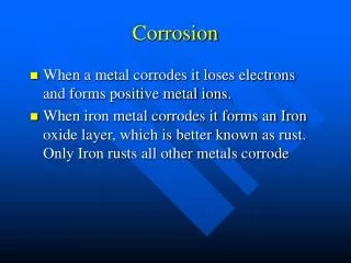
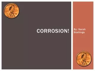
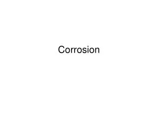
Copyrighted material licensed to Saipem. No further reproduction or distribution permitted. Printed / viewed by: [mohammad.hosseini@saipem.com] @ 2017-03-14 G217 − 16 surface or wave-like surface on a metal that has an even surface before the corrosion (2, 3). 3.2.4 zero-voltage ammeter, ZVA, n—device that imposes a negligibly low voltage drop when inserted into a circuit for measurement of current. 3.2.4.1 Discussion—The ZVA defined in this guide also meets the definition of the zero-resistance ammeter (ZRA) in Guide G199. A typical ZRA is built with inverting operational amplifiers to limit the voltage drop in the current-measuring circuit to a low value. Both ZRA and a simple device formed with a shunt resistor and a voltmeter can be used as a ZVA as long as they do not impose a significant voltage drop (<1 mV) in the current-measuring circuit (see Annex A2 for more information). a new method for monitoring non-uniform corrosion, espe- cially localized corrosion. 4.2 The CMAS technique measures the net anodic current or net cathodic current from each of the individual electrodes (Ia uniform corrosion such as localized corrosion and uneven general corrosion. Therefore, the CMAS technique can be used to estimate the rate of uneven general corrosion and localized corrosion (see Section 5). 4.3 Unlike uniform corrosion, the rate of non-uniform corrosion, especially localized corrosion, can vary significantly from one area to another area of the same metal exposed to the same environment. Allowance shall be made for such varia- tions when the measured non-uniform corrosion rate is used to estimate the penetration of the actual metal structure or the actual wall of process equipment. This variability is less critical when relative changes in corrosion rate are to be detected, for example, to track the effectiveness of corrosion inhibitors in an inhibited system. 4.4 The same as the method described in Guide G96, the CMAS technique described in this guide provides a technique for determining corrosion rates without the need to enter the system physically to withdraw coupons as required by the methods described in Guide G4. 4.5 The same as the methods described in Guide G96, the CMAS technique is useful in systems in which process upsets exor Ic exin Fig. 1), which is the characteristic of non- 4. Significance and Use 4.1 Guide G96 describes a linear-polarization method and an electrical resistance method for online monitoring of corro- sion in plant equipment without the need to enter the system physically to withdraw coupons. These two online monitoring techniques are useful in systems in which process upsets or other problems can create corrosive conditions. An early warning of corrosive attack can permit remedial action before significant damage occurs to process equipment. The two methods described in Guide G96 are suitable for uniform corrosion, but may not be sensitive enough for non-uniform corrosion, especially localized corrosion. This guide describes NOTE 1—The upper section shows the electron flows from the corroding area to the less corroding areas inside a metal when localized corrosion takes place; the lower section shows the electron flows after the anodic and cathodic areas are separated into individual small electrodes and coupled through an external circuit that measures the anodic current (Ia FIG. 1 Principle of CMAS Probe ex) and cathodic current (Ic ex) through each of the individual electrodes (4). 2
Copyrighted material licensed to Saipem. No further reproduction or distribution permitted. Printed / viewed by: [mohammad.hosseini@saipem.com] @ 2017-03-14 G217 − 16 or other problems can create corrosive conditions. An early warning of corrosive attack can permit remedial action before significant damage occurs to process equipment. 4.6 The CMAS technique provides the instantaneous corro- sion rate within 10 to 40 s making it suitable for automatic corrosion inhibitor dosing control. 4.7 The CMAS technique is an online technique and may be used to provide real-time measurements for internal corrosion of pipelines and process vessels, external corrosion of buried pipes and structures, and atmospheric corrosion of metal structures. ment and the coupling joint, which ensures that all the electrodes are at the same electrode potential so that the multiple electrodes simulate the behavior of a one-piece metal. A zero-resistance ammeter (ZRA) is one type of ZVA and can be used for the current measurements in a CMAS probe. A resistor inserted in the circuit and a voltmeter can also be used as the ZVA for the measurements of the current in a CMAS probe because the current from a CMAS electrode is extremely small (typically <1 µA) and produces negligibly low-voltage drop across the resistor (<0.1 mV if the resistor is 100 Ω). 5.1.3 On an anodic electrode, the corrosion current (total dissolution current), Icorr, is equal to the sum of the externally flowing anodic current, Ia flowing anodic currents, Ia tion). Therefore, ex(see Fig. 1) and the internally in(see Annex A1 for more informa- 5. Description of Guide 5.1 Coupled Multielectrode Array Sensor (CMAS) Prin- ciple: 5.1.1 Coupled multielectrode array is a system with mul- tiple working electrodes that are electrically coupled through an external circuit so that all of the electrodes operate at the same potential to simulate the electrochemical behavior of a single-piece metal. The coupled multielectrode arrays have been used for studying the spatial and temporal electrochemi- cal behaviors of metals during corrosion processes (5-7). The CMAS is a coupled multielectrode array used as a sensor for monitoring corrosion. The outputs from a coupled multielec- trode array are the addressable individual currents from all electrodes. The outputs from a typical CMAS probe are usually the maximum corrosion rate and maximum penetration depth derived from the individual currents from the multiple elec- trodes without the need to know the spatial location of the particular electrodes (4, 8). 5.1.2 When a metal undergoes non-uniform corrosion, par- ticularly localized corrosion such as pitting corrosion or crevice corrosion in a corrosive environment, electrons are released from the anodic sites where the metal corrodes and travel within the metal to the cathodic sites where the metal corrodes less or does not corrode (see upper section of Fig. 1) (4). Such phenomenon occurs because of local variations in the microstructure of the metal surface and in the environment or the development of scale layers on the metal surface. If the metal is separated into multiple small pieces (or mini- electrodes), some of the mini-electrodes have properties that are close to the anodic sites and others have properties that are close to the cathodic sites of the corroding metal. When these mini-electrodes are coupled by connecting each of them to a common joint through a multichannel zero-voltage ammeter (ZVA), the electrodes that exhibit anodic properties simulate the anodic areas, and the electrodes that exhibit the cathodic properties simulate the cathodic areas of the corroding metal (see lower section of Fig. 1). The electrons released from the anodic electrodes are forced to flow through the coupling joint to the cathodic electrodes. Thus, the ZVA measures the anodic currents (Ia currents (Ic trodes. The quantitative localized or non-uniform corrosion rates from the individual electrodes may be determined from the anodic currents (4, 5, 8). The reason to use a ZVA to measure the current for each electrode is that the ZVAdoes not impose a potential drop between the electrode under measure- (1) a1Iin a Icorr5 Iex 5.1.4 Because the Ia when the anodic electrode is the most anodic electrode among all the anodic electrodes of the CMAS probe, is often much smaller than its Ia corrosion or localized corrosion environment, the externally flowing current from such anodic electrode of the probe is often used to estimate the non-uniform or localized corrosion current: infor the anodic electrode, especially exat the coupling potential in a non-uniform (2) a Icorr'Iex 5.1.5 In the case of uniform corrosion, however, there would be no physical separation between the anodic electrodes and the cathodic electrodes. The behavior of the most anodic electrode would be similar to the other electrodes in the CMAS probe. In this case, the Ia large and Ia calculate the corrosion rate. Therefore, CMAS technique is not suitable for monitoring the rate of corrosion where the corro- sion is uniformly progressing at all times. The CMAS probe is suitable for monitoring non-uniform corrosion, including un- even general corrosion such as the case for carbon steel in seawater and localized corrosion (see Annex A1 for theoretical basis). In cases of general corrosion in which the corrosion is characterized as both uniform corrosion and uneven general corrosion, the CMAS probe measures the uneven portion of the corrosion. For example, the CMAS probe measures more than 56 % of the corrosion rate for carbon steel in a 0.2 % hydrochloric acid (HCl) solution and more than 22 % of the corrosion rate for carbon steel in a 2 % HCl solution (see Annex A1 for more information). 5.2 Determination of Corrosion Rate (5, 8): 5.2.1 In a corrosion management program for engineering structures, field facilities, or plant equipment, the most impor- tant parameter is the remaining life (often the remaining wall thickness) of the systems. If localized corrosion is of concern, the remaining wall thickness in the most corroded area is often used to evaluate the remaining life. Therefore, the maximum corrosion depth (the corrosion-induced wall thinning at the most corroded area) for non-uniform corrosion (localized corrosion and uneven general corrosion) is often the most important parameter in an operator’s mind. Because the corro- sion depth is a parameter that takes a long time (often many inon the anodic electrode would be exwould be zero, and Eq 2 may not be used to ex) to the more corroding electrodes and cathodic ex) from the less corroding or noncorroding elec- 3
Copyrighted material licensed to Saipem. No further reproduction or distribution permitted. Printed / viewed by: [mohammad.hosseini@saipem.com] @ 2017-03-14 G217 − 16 years) to accumulate, the corresponding parameter that is important to the day-to-day operation would be the maximum non-uniform corrosion rate. 5.2.2 The maximum non-uniform corrosion rate may be derived from the maximum anodic current (assuming no internal current effect) (5): 5.3.2 Similar to the maximum localized corrosion rate, the following equation may be used to calculate the maximum cumulative localized corrosion depth or penetration (cm): CDmax5 QmaxEW⁄~F ρ A! (7) where: Qmax = highest cumulative anodic charge (coulombs) of all the electrodes. 5.3.3 The cumulative anodic charge of each electrode is calculated individually using Eq 6. 5.3.4 Similar to the average corrosion rate, the average anodic charge, Qavg, may be calculated by: Qavg5 ~Σ Qi!⁄n, i from 1 to n where: Qi = anodic charge from the ithelectrode, and n = number of electrodes in the CMAS probe. 5.3.5 In Eq 8, only anodic charge is included. If the charge from an electrode is cathodic, its anodic charge is set to zero in the calculation. Thus, the average non-uniform corrosion penetration depth, CDavg, may be calculated by: CDavg5 ~Qavg!EW⁄~F ρ A! 5.3.6 The localized penetration depth ratio, fdepth, may be defined as the ratio of the maximum non-uniform penetration depth to the average non-uniform corrosion penetration depth: CRmax5 ImaxEW⁄~F ρ A! (3) where: CRmax = calculated maximum penetration rate (cm/s), Imax = maximum anodic current or the most anodic current, F = Faraday constant (96485 C/mol), A = surface area of the electrode (cm2), ρ = density of the alloy or electrode (g/cm3), and EW = equivalent weight (g/mol) (see Practice G102). (8) 5.2.3 Eq 3 assumes that the corrosion on the most corroded electrode is uniform over the entire surface. Because the surface area of one electrode is usually between 1 and 0.03 mm2in a typical CMAS probe, the prediction of the penetra- tion rate or localized corrosion rate by assuming uniform corrosion on the small electrode is realistic in most applica- tions. 5.2.4 The average non-uniform corrosion rate, CRavg, may be derived from the average anodic current, Iavg, which is the sum of anodic currents divided by the number of electrodes on the CMAS probe: (9) fdepth5 CDmax⁄CDavg (10) CRavg5 IavgEW~F ρ A! (4) 5.3.7 Similar to the pitting factor described in Guide G46, the localized corrosion penetration depth ratio indicates the severity of localized corrosion. The fdepthrepresents how much deeper the deepest pit is than the average depths of the pits. The average non-uniform corrosion depth (CDavg) in Eq 10 is not the average depth of metal loss as defined in Guide G46. In a uniform corrosion case, the uniform corrosion depth may be high, but the average non-uniform corrosion depth may be zero. Eq 4 is valid only if the areas of all the electrodes are equal. Otherwise, a weighted average according to the areas of the electrodes should be used. 5.2.5 The localized rate ratio, frate, is defined as the ratio of the maximum localized corrosion rate to the average non- uniform corrosion rate. It can be expressed by: frate5 CRmax⁄CRavg (5) The average non-uniform corrosion rate is not the average metal corrosion rate because it does not include the portion of uniform corrosion rate. In a uniform corrosion case, the uniform corrosion rate may be high, but the average non- uniform corrosion rate may be zero. 6. Limitations and Interferences 6.1 The technique is not applicable if the corrosion is purely uniform. In this case, all electrodes are corroding at the same pace and the Ia zero and the corrosion current, Icorr, is equal to the internal currents (see Eq 1).Apurely uniform corrosion case is rare and most of the general corrosion cases observed in laboratories and industrial fields exhibit a certain degree of uneven general corrosion. Examples of such cases are carbon steel or alumi- num in a dilute hydrochloric acid solution where uniform corrosion is dominant but uneven general corrosion is still present (see Annex A1). In cases in which uniform corrosion and uneven general corrosion are both present, the CMAS technique underestimates the corrosion rate because this tech- nique only measures the uneven portion of the general corro- sion rate. 6.2 CMAS probes with flush electrodes embedded in insu- lators have high susceptibility to the effect of crevice corrosion. This may be alleviated by applying a coating on the electrodes before the electrodes are embedded in the insulator. 5.2.6 The localized rate ratio indicates how much higher the non-uniform corrosion rate on the most corroding electrode (which simulate the penetration rate of the fastest growing pit on the surface of a metal in the case of pitting corrosion) is than the average corrosion rate. 5.3 Determination of Corrosion Penetration Depth (5, 8): 5.3.1 The corrosion depth or penetration is related to the total damage accumulated in a given time period. The corro- sion depth of the ithelectrode may be derived from the cumulative anodic charge that can be obtained by integrating the corrosion current through the electrode from time zero to time, t: ex(see Fig. 1) from any of the electrodes will be Qi5*Ii~t!dt (6) where: Qi = cumulative anodic charge of the ithelectrode. 4
Copyrighted material licensed to Saipem. No further reproduction or distribution permitted. Printed / viewed by: [mohammad.hosseini@saipem.com] @ 2017-03-14 G217 − 16 6.3 Electron-conductive deposits (such as iron sulphides) can cause a short-circuiting (bridging) effect for measurement methods based on electrical resistance or electrochemical principles. For example, the electron-conductive deposits cause the electrical resistance method (see Guide G96) to show a lower metal loss rate or even a negative metal loss rate. For the CMAS technique, closely packed small electrodes are also susceptible to the bridging of the electrodes by the electron- conducting deposits. This may be alleviated by using individu- ally insulated electrodes that project above the surface of the probe (also called fingered electrodes) so that the interfacial path between each electrode becomes significantly larger (9). 6.9 Corrosion rates may be affected by flow velocity. Consequently, probe electrodes should be installed in a veloc- ity typical of the plant conditions. Caution should be exercised in any laboratory tests to reproduce typical velocities and keep the test fluid representative of plant conditions by preventing an unrepresentative buildup of corrosion products in solution or depletion of dissolved oxygen. Localized corrosion usually occurs at locations with stagnant flow or deposits. The sensing surface should be exposed to the stagnant flow if it is used to monitor the worst-case localized corrosion in a plant system. 6.10 Where flow dynamics or process fluid separation at a pipe or vessel wall are particularly critical to the corrosion process, a flush-mounted probe may be more desirable than a probe with electrodes positioned near the center of the pipe or vessel. 6.4 The CMAS technique may be more affected by electri- cal or magnetic noises from the process and local environment because the current signals from a CMAS probe are typically low (1 pA to 1 µA) for each electrode. The noise effect may be minimized by the use of shielded cables and a noise-rejection CMAS instrument and proper selection of the installation location. The CMAS probe, CMAS instrument, and the cabling should be such that they are away from the electrically noisy sources such as power cables, heavy duty motors, and heavy duty pumps. 6.11 The CMAS measurement only determines metal lost caused by electrochemical corrosion and not metal lost by mechanical removal (such as erosion) or local chemical reac- tion (such as dry-air oxidation). In the case of erosion corrosion, only the electrochemical-induced corrosion compo- nent will be measured by the CMAS technique. This technique is also not capable of detecting the pitting that results from non-electrochemically active inclusions in the metal in which case the formation of the pit does not involve the release of electrons. 6.5 The CMAS technique calculates the maximum non- uniform corrosion or localized corrosion rate by assuming that the corrosion on the most anodic electrode is uniform. In reality, the electrode size may not be as small as a single pit during the initiation stage and the corrosion on the most anodic electrodes may not be uniform. The CMAS probes with smaller electrode surface areas (<1 mm2) should be used to minimize the size effect on the measurement of the non- uniform corrosion rate. When the size is small (<1 mm2), the corroded area is more likely to occupy the whole surface during the propagation stage of localized corrosion, especially after the corroded area has grown to a certain depth that may compromise the integrity of the plant equipment. 6.12 When first introduced into a system, the initial corro- sion rates on a newly polished probe are usually higher than the longer-term corrosion. Establishment of the probe-sensing electrode surface typical of the plant system by passivation, oxidation, deposits, or inhibitor film buildup may vary from hours to several days. Therefore, the corrosion rates occurring on the probe electrodes during the first few hours or days of exposure may not be typical of corrosion occurring in the system. Preconditioning of electrodes for the surface to corre- spond to the metal surface after the chemical treatment of the plant may reduce this transient effect. 6.6 As an electrochemical method, the presence of other secondary reactions that are not directly related to corrosion but involve charge transfer may affect the measurements. In cases in which the other secondary reactions may be present, the potential of the coupling joint of the CMAS probe (the potential of the CMAS electrodes) should be measured and compared with the electrode potentials of the secondary reactions that are published or measured in the laboratories with electrodes similar to those of the CMAS probe. If the coupling potential of the CMAS probe is close to the potentials of the secondary reactions, the corrosion rate data from the CMAS probe should be carefully evaluated before use. 7. Apparatus 7.1 CMAS Probes: 7.1.1 The CMAS is composed of multiple electrodes with chemical and metallurgical properties closely matching those of the plant systems or metals under study. For corrosion monitoring or corrosion studies in a laboratory, the number of electrode can be as many as 55 or even 100 (6, 7, 10, 11). For corrosion monitoring in a plant, however, the number of electrodes in a CMAS probe is usually 8 to 25 because the costs of the CMAS probe and CMAS instruments usually increase with the increase in the number of electrodes (12, 13, 14). 7.1.2 The electrodes in a CMAS probe are usually flush mounted in an epoxy or a high-temperature insulator and the length of the electrodes is usually more than 2.5 cm. The probe’s sensing surface can be polished and reused until a depth that corresponds to the length of the electrodes embed- ded in the insulator. 7.1.3 Side surfaces of CMAS electrodes should be pre- coated before being imbedded in the insulator to minimize 6.7 Repolishing of the CMAS probe surfaces should be avoided if the system being monitored is experiencing corro- sion under deposits. This will improve the representativeness of the probe surfaces to the plant surfaces of interest. 6.8 Since the corrosion rate is usually temperature dependent, results will be comparable only for the alloy at the process temperature to which the probes are exposed. In a heat transfer environment, actual plant metal temperatures may be significantly different from that of the test probe. 5
Copyrighted material licensed to Saipem. No further reproduction or distribution permitted. Printed / viewed by: [mohammad.hosseini@saipem.com] @ 2017-03-14 G217 − 16 crevice corrosion taking place between the side surface of the electrodes and the insulator. The coating material should be compatible with the process environments. For example, epoxy coating may be used if the application temperature is below 100°C and diamond-like carbon (DLC) coating may be used when system temperature is beyond 100°C (15). The DLC is an amorphous carbon material that displays some of the typical properties of diamond and has excellent corrosion resistance in many corrosive environments at high temperatures. 7.1.4 Probe construction and sealing materials should be compatible with the process fluid. 7.1.5 Probes for corrosion monitoring in pressurized pro- cesses may be retrievable and nonretrievable. The retrievable design enables the installation of the probes, or removal of the probes for inspection and cleaning, under operating conditions except where operational safety precludes this. There are various designs of the retrievable probes and some of them are called retractable probes in the industry. All these different designs are considered retrievable probes in this guide as long as they can be installed or removed under operating conditions. Any retrievable probe installed in a pressurized system must be reviewed by competent engineers for safety evaluation. across the current-measuring resistors for every electrode is negligibly low but high enough for reliable measurement by the voltmeter. 7.2.3 In plant or field applications, the multichannel ZVA should have the mechanism to disconnect a faulty electrode from the coupling joint in case it is statistically identified as an outlier.An outlier electrode may be caused by the impurities or microstructure defects in the particular electrode. 7.2.4 In plant or field applications, the continuous maximum non-uniform corrosion rate is a more critical parameter and should be used for detecting system upsets or effectiveness of corrosion mitigation programs such as inhibitor dosing or cathodic protection. The cumulative maximum penetration depth should be used for equipment life evaluations. 7.2.5 For field applications, an automatic continuous moni- toring system may be stand-alone systems or interfaced with other process controllers or both. 7.3 Probe Preparation: 7.3.1 The sensing surface should be kept clean during handling and installation by the use of clean gloves or clean paper to avoid causing additional corrosion. Before initial installation, the electrode on the sensing surface should be polished to 150 to 400 grit either manually or on a polishing wheel. Degreasing is necessary to complete the cleaning procedure. Practice G1 provides guidance on proper methods of cleaning various materials. 7.3.2 When moving probes from one system to another, it is recommended that the electrode-sensing surface of the probe be repolished to remove the oxide or inhibitor films. 7.2 CMAS Monitoring Instruments: 7.2.1 Both dedicated CMAS instruments and general pur- pose ZVA can be used for measuring the currents from a CMAS probe. Typical dedicated CMAS instruments give direct readings for maximum non-uniform corrosion rates and aver- age non-uniform corrosion rates. Some CMAS instruments also calculate the cumulative maximum penetration caused by localized corrosion to represent the metal loss or corrosion history by keeping track of the anodic currents flowing through each electrode. When a general purpose multichannel ZVA is used, the maximum non-uniform corrosion rate and the cumu- lative maximum corrosion depth can be manually derived according to 5.2 and 5.3. 7.2.2 The multichannel ZVA can be a multichannel ZRA or a series of shunt resistors directly inserted in the circuit between each electrode and the coupling joint. When shunt resistors are used, a precision multichannel voltmeter should be used to measure the voltage across each resistor and the current flowing through the shunt resistor is derived using Ohm’s Law. No matter which type of measuring device is used, the voltage across the current-measuring device should be negligibly low compared to the open circuit potentials among identical elec- trodes which are usually from 20 to 300 mV (7, 8) in the corrosive environments that cause uneven general corrosion or localized corrosion. When the variations of open circuit poten- tials among the different electrodes are higher than 20 mV, the voltages across a typical ZVAof less than 0.5 mV, regardless of the type of ZVA, are usually acceptable because the error caused by such low voltages is less than 5 % of the theoretical value (16). Because the current flowing through the individual electrodes varies from one electrode to another, a group of parallel resistors and a switching means may be used between each electrode and the coupling joint so that the effective value of the resistance may be auto-changed such that the voltage 8. Probe Installation 8.1 For laboratory application, the probe should be installed into the testing system in a position that simulates the test specimen in the corrosive environment as closely as possible. 8.2 For plant application, the CMAS probe should be installed into the plant in a position as representative of the corrosive environment as possible without causing deleterious effects to the plant such as a major flow restriction. 8.3 The probe should be installed so that the electrodes face or do not face the flow in a similar manner as the monitored equipment in a plant or a specimen in a testing unit. 8.4 Do not install the probe in a section where temperature or flow conditions or both are not representative of the system under examination. 8.5 If a bypass loop is being used for housing the CMAS probe, ensure that conditions in the loop are representative of those in the actual system. 8.6 For long-term monitoring, probes should be removed at regular intervals to inspect for electrode deterioration, damage, or bridging of electrodes and ensure continued quality of corrosion rate data. As mentioned in 6.7, however, repolishing of the CMAS probe surfaces should be avoided if the system being monitored is experiencing corrosion under deposits. This will improve the representativeness of the probe surfaces to the plant surfaces of interest. 6
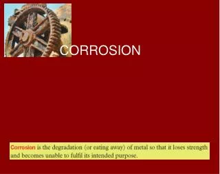
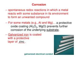
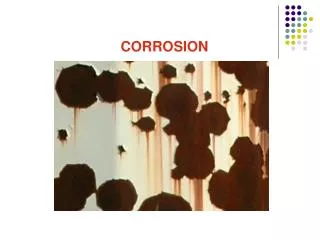
Copyrighted material licensed to Saipem. No further reproduction or distribution permitted. Printed / viewed by: [mohammad.hosseini@saipem.com] @ 2017-03-14 G217 − 16 8.7 Coupons should always be installed in parallel with the CMAS probes for validation of the probe signals whenever possible. If the condition allows, multiple coupons should be used because corrosion, especially localized corrosion, is highly stochastic in nature. The same metal in the same solution may be corroded to different depths at different locations because of the variations in the microstructure of the metal and the variations in the local environment surrounding the metal. Refer to Guide G4 for guidance on the installation of the coupons in plant equipment. 8.8 Shielded cable should be used for the connection be- tween the CMAS probes and CMAS instruments to avoid the fluctuations that may be induced by noise from the environ- ment. redox species, the coupling potential may tell the user that the corrosion rate from the CMAS probe is not affected by the redox species if the coupling potential is far away from the potential of the redox species. 9.2 Dedicated CMAS Instruments: 9.2.1 These instruments are available in various single- probe or multi-probe configurations that may be stand-alone systems or interfaced with process computers or both. These units provide continuous information on instantaneous corro- sion rates. 9.2.2 The CMAS probes should be connected to the CMAS instruments according to the manufacturer’s instructions. 9.2.3 The surface area, density, and equivalent weight of the electrodes that are required by the instrument to calculate the direct readout of corrosion rate (see 5.2 and 5.3) should be entered into the CMAS instruments. The accuracy of the surface area measurements should be 10 % or better. 9.2.4 The CMAS instrument outputs are usually maximum non-uniform corrosion rate and average non-uniform corrosion rate in µm/year (or mpy) and maximum penetration depth and average penetration depth in µm (or mil). Some of the instruments may also give a real-time localized corrosion rate ratio (Eq 5) and the localized corrosion penetration depth ratio (Eq 10). 9.2.5 Unless confirmed by other methods such as pit depth measurements on exposed coupons and ultrasonic measure- ments of the equipment wall, the maximum penetration depth should not be used to assess the remaining life of the equipment because of the stochastic nature of localized corro- sion (see Section 10). 9.2.6 Generally, the most useful form of data is the graph of corrosion rate versus time for each monitored point. 9. Procedure 9.1 General Purpose Multichannel ZVA: 9.1.1 Because of the large number of current signals from a CMAS probe, the multichannel ZVA should be interfaced with a proper data acquisition system so that the data sampling is automated and the acquired data are saved into a computer hard drive for further analysis. 9.1.2 The multichannel ZVA should have sufficient resolu- tion to measure the expected corrosion rate from the CMAS probe. For example, the current corresponds to 10 µm/year for a carbon steel probe with 1-mm diameter electrodes that are flush mounted in an insulator is approximately 10 nA. 9.1.3 Connect the electrodes of the CMAS probe to the multichannel ZVA as shown in Fig. 2. The coupling joint (where all the electrodes are joined together) should be made accessible for the measurement of the coupling potential of the CMAS probe against a reference probe installed in the same fluid. The measurement of the coupling potential is not required for the corrosion rate calculation, but the coupling potential may provide additional useful information. For instance, when a CMAS probe is used in a system containing 9.3 Corrosion Monitoring under Cathodic Protection Con- ditions: FIG. 2 Wiring Diagram for CMAS Probes to Multichannel ZVA Formed with Multiple ZRAs (a) (7) and Multiple Shunt Resistors (b) (8) 7
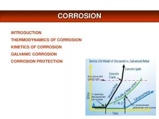
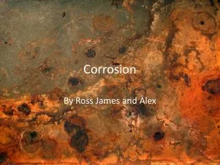
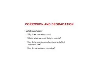
Copyrighted material licensed to Saipem. No further reproduction or distribution permitted. Printed / viewed by: [mohammad.hosseini@saipem.com] @ 2017-03-14 G217 − 16 10. Interpretation of Results 10.1 Variability of Data—Because of its stochastic nature, the localized corrosion rate for the same metal in the same bulk environment may vary by a factor of five or higher (17). The variation in the general corrosion rate is usually smaller, but a factor of two has been reported (18). 10.2 Detection of Process Upset—The large variation in corrosion rates from a single probe makes the technique less suitable for determination of absolute corrosion rate but useful in determining the relative change in corrosion rates and process upset detection. 10.3 Use of Multiple Probes and Multiple Coupons— Careful interpretation is necessary in correlating the non- uniform corrosion rates from the CMAS probes with actual metal corrosion in a test system or plant. Multiple CMAS probes, along with coupons (see Guide G4), should be used for determination of the absolute corrosion rate based on statistical principles. A statistical approach should be used to establish reliability as to estimation of service life in a plant (see G16). 9.3.1 CMAS probes can be used to monitor the effectiveness of cathodic protection. The probe should be installed close to a metal system that is protected and the coupling joint shall be connected to the protected metal system. Under this condition, the probe-sensing electrodes are at the same electrode potential as the protected metal. The different electrodes of the CMAS probe simulate the different corrosion sites on the metal. When the protection potential is sufficiently low, none of the elec- trodes on the CMAS probe would exhibit anodic behavior and the corrosion current from the CMAS system is near zero (4). 9.3.2 The sensing tip of the CMAS probe should be installed near the worst-case location. For example, the probe should be installed in the location that is the most difficult for the cathodic protection current to reach. 9.4 Calibration and Zero Check—The CMAS probes should be checked in standard environments before installation and whenever the probes are taken out for inspection. The standard environments may include dry air in which the corrosion rate should be near zero, simulated seawater (with ~3.5 % sodium chloride) saturated with air for carbon steel (in which case, the maximum non-uniform corrosion rate for carbon steel should be from 0.2 to 3 mm/year (5)), and a ferric chloride solution as described in Test Methods G48 (Method A or B, 6 % FeCl3by mass) for stainless steel or nickel-based alloys (14). 11. Keywords 11.1 CMAS; corrosion monitoring; coupled multielectrode; coupled multielectrode array sensor; crevice corrosion; local- ized corrosion monitoring; on-line corrosion monitoring; pit- ting corrosion ANNEXES (Mandatory Information) A1. THEORETICAL BASIS OF CMAS PROBES FOR NON-UNIFORM CORROSION RATE MEASUREMENTS A1.1 In Fig. A1.1, the polarization curves for the most anodic electrode and the polarization curves for the combined supporting cathodic electrodes of a CMAS probe are shown (1, 5). Because localized corrosion often involves small areas of corroded anodic sites accompanied by large areas of cathodic sites, the anodic current from the most anodic electrode is usually supported by several cathodic or less anodic electrodes. The thin solid curves represent the dissolution and reduction polarization behaviors on the most anodic electrode, respec- tively. The thick solid curves represent the combined dissolu- tion and reduction polarization behaviors, respectively, on the supporting cathodic electrodes as if these cathodic electrodes are coupled as a single electrode. The thick dashed lines represent the reduction curve for all electrodes (the most anodic electrode and the cathodic electrodes that provide the cathodic currents to support the anodic current on the most anodic electrode) and the dissolution current for all these electrodes on the CMAS probe, respectively. For a passive metal, in the cathodic area (or the cathodic electrodes in a CMAS probe) where no localized corrosion has initiated, the anodic current is usually extremely low because of the protec- tive layer of the oxide film formed on the metal and the corrosion potential for the cathodic electrodes, Ec (or noble). For the anodic electrode where localized corrosion has initiated and the protective layer has been compromised, however, the anodic current is usually high and the corrosion potential for the anodic electrode, Ea Note in Fig. A1.1, the cathodic current on the combined cathodic electrodes is significantly higher than that on the anodic electrode. This is because we have assumed that the surface area on the anodic electrode is significantly smaller than that of the combined cathodic electrodes (one anodic electrode versus many cathodic electrodes). In addition, the cathodic reactions deep in an anodic pit on the anodic electrode require more efforts for the reactants (O2or H+) to overcome the mass transfer barriers. corr, is high corr, is low (or active). A1.2 When the most anodic electrode and the combined cathodic electrodes are coupled, the potential changes to a new value, Ecoup(or Ecorrfor all these coupled electrodes) and the total anodic dissolution currents equal the total cathodic currents (see the thick dashed lines in Fig. A1.1): 8
Copyrighted material licensed to Saipem. No further reproduction or distribution permitted. Printed / viewed by: [mohammad.hosseini@saipem.com] @ 2017-03-14 G217 − 16 FIG. A1.1 Schematic Diagram for the E-to-Log I (Log of Current) Curves on the Most Anodic Electrode and Several Cathodic Electrodes that are Connected Together on a CMAS (5) to the internally flowing cathodic currents (or the internal reduction current), Ia (A1.1) c5 Iin a1Ic Icorr1Iin in, which is Eq 1 (see Section 4). where: Icorr = corrosion current (total dissolution current) on the most anodic electrode, Ic in = internal dissolution (anodic) current on all the ca- thodic electrodes (anodic current that flows within all the cathodes), Ia in = internal reduction current on the anode (also the cathodic current that flows within the anode), and Ic = cathodic current on the combined cathodes. A1.4 The upper bound of the internal currents, Ia effect of Ia tion method for the most anodic electrode. Table A1.1 shows typical results for aluminum and carbon steel CMAS probes obtained in simulated seawater and dilute hydrochloric solu- tions (1). In all cases in which the metals exhibited typical localized corrosion or non-uniform general corrosion, the Ia values are much lower than the Ia on the calculation of Icorrusing Eq 2 (Section 4) is less than 10 %. in, and the inon Icorrwas estimated using the Tafel extrapola- in exvalues and the effect of Ia in A1.3 As shown in Fig. A1.1, the corrosion current, Icorr, is equal to the sum of the externally flowing anodic currents, Ia and the internally flowing anodic currents, which are also equal ex, TABLE A1.1 Externally Measured Anodic Currents, Internal Anodic Currents, and Corrosion Currents on the Most Anodic Electrodes for Aluminum and Carbon Steel CMAS Probes (1) NOTE 1—The electrodes of the CMAS probe were held at open-circuit potential (coupling potential of the probe) for about 2 h prior to the polarization tests. Al in 3 % NaCl 427 <25.0 452 >0.94 <6 % CS in 3 % NaCl 2600 <210 2810 >0.93 <7 % Non-uniform general corrosion Al in 0.2 % HCl 436 <1900 2340 >0.19 <81 % CS in 2 % HCl 1100 <3900 5000 >0.22 <78 % CS in 0.2 % HCl 794 <630 1420 >0.56 <44 % Iaex(nA) Iain(nA)A Icorr(nA)B Iaex/Icorr (Iain/Icorr)C Corrosion Mode Localized corrosion Uniform corrosion Uniform corrosion Uniform corrosion AIain—These values were derived with the Tafel extrapolation method and they are the upper bounds of the Iainvalues. BIcorr—Corrosion current on most anodic electrode (Icorr= Iaex+ Iain). CIain/Icorr—Effect of internal current. 9
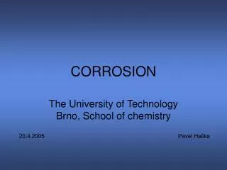
Copyrighted material licensed to Saipem. No further reproduction or distribution permitted. Printed / viewed by: [mohammad.hosseini@saipem.com] @ 2017-03-14 G217 − 16 A2. ZERO-VOLTAGE AMMETER (ZVA) AND ZERO-RESISTANCE AMMETER (ZRA) A2.1 Definitions of ZVA and ZRA—In 3.2.4, a ZVA is defined as a device that imposes a negligibly low voltage drop when inserted into a circuit for measurement of current. This definition is essentially the same as the definition of ZRA in Guide G199—electronic device used to measure current with- out imposing a significant IR drop by maintaining close to 0-V potential difference between the inputs. is astonishingly high when the input current is small. For example, when the input current is 1 nA, which is a typical value of the coupling current in a CMAS probe, the voltage- to-current ratio is actually 500 000 ohm when the input voltage is 0.5 mV. A2.4 By comparing the definitions of ZVA and ZRA in A2.1, the ZRA can be used as the ZVA and many researchers have used the ZRA in their work with the coupled multielec- trode systems. The device built with a simple shunt resistor and a voltmeter has also been used by many researchers in their work with CMAS probes. With the shunt-resistor approach, the voltmeter is used to measure the small voltage drop across the shunt resistor to derive the current. As long as the voltage drop across the shunt resistor is negligibly low (less than 0.5 mV for example), the device built with a shunt resistor can be used as the ZVA for the CMAS systems. A2.2 The commonly accepted concept for ZRA is that it is built with an operational amplifier (Op-Amp) as shown in Fig. A2.1 and its input resistance is zero when it is used as an ammeter. If Op-Amp is ideal, the potential at the inverting terminal (Vp–Vn) is zero and the ratio of the input voltage drop to the measured current is zero. A2.3 In reality, Op-Amps are not ideal and do have input voltage. For example, every Op-Amps has an input offset voltage (VOS) which is defined as the small differential voltage that must be applied to the input of an Op-Amp (Vp–Vn) to produce zero output (Vout). As a matter of fact, the input offset voltage is one of the most important parameters that are reported in manufacturer’s product specification sheets. The input offset voltage of general-purpose Op-Amps usually varies between -0.5 mV and +0.5 mV, but may be as large as 62 mV. When general-purpose Op-Amps are used to build a ZRA, the input voltage must be the input offset voltage when the readout of the ZRA is zero. In addition, the input offset voltage may drift with time. Commercial potentiostats may impose an input voltage between -1 mv and +1 mV when used as a ZRA according to some manufacturers’ specifications. While the change of electrode potential caused by a ZRA that has an input voltage of 1 mV is often negligibly small, the voltage-to-current ratio corresponds to this small input voltage A2.5 Even though a real-world ZRA may have a voltage- to-current ratio as high as 500 000 ohms, an ideal ZRA does have a zero voltage-to-current ratio. It is understandable to call the current-measuring device built with the Op-Amps a ZRA. However, it is not appropriate to call the current-measuring device built with the shunt resistors a ZRA because the values of the shunt resistors can never be zero. To avoid the confusion, the devices used for the measurement of the currents in CMAS probes have been called ZVA (1) because both ZRA and the device built with a simple shunt resistor can provide the same function. This guide defines all devices that can be used for CMAS probes as ZVA. The term ZVA applies to both the ZRA and the device built with shunt resistors as long as such devices do not impose a significant voltage drop in the measuring circuit. FIG. A2.1 Basic Circuit of a Zero-Resistance Ammeter for the Measurement of Current Without Imposing a Significant IR Drop by Main- taining Close to 0-V Potential Difference Between the Inputs 10
Copyrighted material licensed to Saipem. No further reproduction or distribution permitted. Printed / viewed by: [mohammad.hosseini@saipem.com] @ 2017-03-14 G217 − 16 REFERENCES (1) Yang, L., Chiang, K. T., Shukla, P. K., and Shiratori, N., “Internal Current Effects on Localized Corrosion Rate Measurements Using Coupled Multielectrode Array Sensors,” Corrosion, Vol 66, 2010, p. 115005. (2) Champion, F. A., J. Inst. Met., Vol 69, 1943, pp. 47–66. (3) Greene, N. D., and Fontana, M. G., Corrosion, Vol 15, 1959, pp. 25t–31t. (4) Sun, X. and Yang, L., “Real-Time Monitoring of Localized and General Corrosion Rates in Drinking Water Utilizing Coupled Mul- tielectrode Array Sensors,” CORROSION/2006, Paper No. 06094, Houston, TX, NACE, 2006. (5) Yang, L., “Multielectrode Systems,” in Techniques for Corrosion Monitoring, L. Yang, Ed., Woodhead Publishing, Cambridge, United Kingdom, 2008, Chap. 8. (6) Fei, Z., Kelly, R. G., and Hudson, J. L., “Spatiotemporal Patterns on Electrode Arrays,” J. Phys. Chem., Vol 100, 1996, pp. 18986–18991. (7) Tan, Y. J., “Monitoring Localized Corrosion Processes and Estimating Localized Corrosion Rates Using a Wire-beam Electrode,” Corrosion, Vol 54, No. 5, 1998, pp. 403–413. (8) Yang, L., Sridhar, N., Pensado, O., and Dunn, D., “An In-situ Galvanically Coupled Multi-Electrode Array Sensor for Localized Corrosion,” Corrosion, Vol 58, 2002, p. 1004. (9) Yang, L., Sun, X., and Barnes, R., “Coupled Multielectrode Array Sensor with Coated, Fingered Electrodes for Corrosion Monitoring in Oil-Water Mixtures and Gas Systems Containing Hydrogen Sulfide,” CORROSION/2014, Paper No. 06094, Houston, TX, NACE, 2014. (10) Hinds, G. and Turnbull, A., “Novel Multi-electrode Test Method for Evaluating Inhibition of Underdeposit Corrosion. Part 1: Sweet Conditions,” Corrosion, Vol 66, No. 4, 2010, p. 046001. (11) Cong, H., Bocher, F., Budiansky, N. D., Hurley, M. F., and Scully, J. R., “Use of Coupled Multi-Electrode Arrays to Advance the Under- standing of Selected Corrosion Phenomena,” Journal of ASTM International, Vol 4, No. 10, Paper ID JAI101248, 2007. (12) Yang, B., Marinho, F. J., and Gershun, A. V., “New Electrochemical Methods for the Evaluation of Localized Corrosion in Engine Coolants,” Journal of ASTM International, Vol 4, No. 1, 2007. (13) Colbert, R., and Reich, R., “Corrosion Monitoring of a Water Based Rolling Facility with Coupled Multielectrode Array Sensors and the Correlations with Other Process Variables: Conductivity, pH, Temperature, Dissolved Oxygen and Corrosion Potential,” CORROSION/2008, Paper 08295, Houston, TX, NACE, 2008. (14) Yang, L., Sridhar, N., Brossia, C. S., and Dunn, D. S., “Evaluation of the Coupled Multielectrode Array Sensor as a Real Time Corrosion Monitor,” Corrosion Science, Vol 47, 2005, pp. 1794–1809. (15) Chiang, K. T., and Yang, L., “High-Temperature Electrochemical Sensor for Online Corrosion Monitoring,” Corrosion, Vol 66, 2010, p. 095002. (16) Yang, L., “Effect of Voltage between Electrodes of a Coupled Multielectrode Array Sensor on Corrosion Rate Measurement,” CORROSION/2016, Paper No. 7911, Houston, TX, NACE, 2016. (17) Southwell, C. R., Hummer, C. W., Jr., and Alexander, A. L., “Corrosion of Metals in Tropical Environments, Part 7—Copper and CopperAlloys—Sixteen Years’Exposure,” NRL Report 6452, Naval Research Laboratory, Washington, DC, 1966, p. 4. (18) Dorsey, et al, CORROSION/2002, Paper No. 02009, Houston, TX, NACE, 2002, p. 14. ASTM International takes no position respecting the validity of any patent rights asserted in connection with any item mentioned in this standard. Users of this standard are expressly advised that determination of the validity of any such patent rights, and the risk of infringement of such rights, are entirely their own responsibility. This standard is subject to revision at any time by the responsible technical committee and must be reviewed every five years and if not revised, either reapproved or withdrawn. Your comments are invited either for revision of this standard or for additional standards and should be addressed to ASTM International Headquarters. Your comments will receive careful consideration at a meeting of the responsible technical committee, which you may attend. If you feel that your comments have not received a fair hearing you should make your views known to the ASTM Committee on Standards, at the address shown below. This standard is copyrighted by ASTM International, 100 Barr Harbor Drive, PO Box C700, West Conshohocken, PA 19428-2959, United States. Individual reprints (single or multiple copies) of this standard may be obtained by contacting ASTM at the above address or at 610-832-9585 (phone), 610-832-9555 (fax), or service@astm.org (e-mail); or through the ASTM website (www.astm.org). Permission rights to photocopy the standard may also be secured from the Copyright Clearance Center, 222 Rosewood Drive, Danvers, MA 01923, Tel: (978) 646-2600; http://www.copyright.com/ 11