Download
1 / 74
750 likes | 937 Views
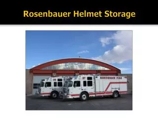
Rosenbauer Chassis Electrical Control System. V-MUX. What is it?

E N D
V-MUX What is it? • The Weldon V-MUX is a central control system utilized by the new Rosenbauer engines to manage and control the electrical system on the apparatus and provide a centralized place for the operator to activate and deactivate most of the electrical components on the apparatus. • The screen is located adjacent to the driver’s seat and will sometimes also be referred to as the Vista Display. • Most of the normal chassis operations can be found on one of several screens displayed on the V-MUX.
V-MUX/Vista Display Features Physical buttons across the bottom of the display are used to navigate between screens
V-MUX/Vista Display Features Virtual switches (touch screen)
V-MUX/Vista Display Features Physical buttons adjacent to screen
V-MUX/Vista Display Features Touching button or screen performs the same function
V-MUX/Vista Display Features Both cause a color change as a response to input from operator
V-MUX/Vista Display Features • Door ajar/do not move apparatus situation visual display • Seat Belt status Display • Digital Voltage monitoring • Load management system • Auto and manual high idle operations • Chassis HVAC automatic climate control • Input for video displays from reverse and blind spot camera • Time and Date display
Physical Buttons Across Bottom of Display • E-Master • Warning light Menu • Home screen • Secondary Menu • System Info • Heat/AC • High Idle
E-Master If a light is deactivated from the warning light menu screen, it will default back on next time the E-master is cycled off and then on. This ensures that all warning lights are on each time the E-master is activated. • Once activated, warning lights can be individually deactivated and reactivated by using the buttons in the warning light menu screen. • If the use of specific lights are required but not all lights are needed, they can be individually activated and deactivated from the warning light menu. Activates and deactivates all warning lights on the apparatus with the touch of one button.
Warning Light Menu (Page 1) Roof Lights – Activates all three light bars on roof. Even though switch is on, white lights will only come on when parking brake is released.
Warning Light Menu (Page 1) Opitcom – Activates opticom. Even though switch is on, opticom (infarred) will only come on when parking brake is released.
Warning Light Menu (Page 1) Front Warning – Activates lower front warning lights on front of cab, 2 colored and 2 clear or white lights. Even though switch is on, white lights will only come on when parking brake is released.
Warning Light Menu (Page 1) High Beam Flash – Activates high beam flash. Even though switch is on, head lights will only flash when parking brake is released.
Warning light Menu (Page 1) Siren/Horn – Selects whether the horn button on the steering wheel will operate the electric city horn or change siren tones.
Warning Light Menu (Page 1) Next – Advances to second warning light menu screen (Page 2)
Warning Light Menu (Page 2) Upper Side Warning – Activates upper lights on sides of body
Warning Light Menu (Page 2) Lower Side Warning – Activates lower lights on sides of bumper, cab, and body
Warning Light Menu (Page 2) Upper Rear Warning – Activates upper lights on rear of apparatus
Warning Light Menu (Page 2) Lower Rear Warning – Activates lower lights on rear of apparatus
Warning Light Menu (Page 2) Previous Screen – Returns to first warning light menu screen (Page 1)
Home Screen Headlights- Will cycle through head light low beam on, head lights off, marker lights on.
Operational Note Headlights • Head lights always default on and will be turned back on automatically when master battery switch is cycled off and then on, even if head lights were left in the off position when battery master was turned off
Home Screen Dimmer – Adjusts brightness of display and gauges. Available settings: max-normal-dim-night. This dimmer setting always defaults to max when the battery master is cycled off and then back on.
Home Screen • Dome lights – Activates all white dome lights inside cab. • Note: white dome lights are also activated by respective cab door switches and can be individually activated by pushing the white lens on the light. Red dome lights can be individually activated by pushing the red lens on the light.
The red dome lights in the crew cab can also be activated by using the rocker switch on the back wall of the cab between the forward facing seats.
Home Screen Mud/Snow – Activation of this switch will allow additional wheel slip when these conditions are encountered. This switch defaults off whenever the battery master is cycled.
Home Screen Message Acknowledge – Acknowledges messages displayed in center section.
Home Screen Alarm Silence – Provides a 15 second silence of alarm activated by a do not move apparatus situation and seat belt violation.
Home Screen Perimeter Lights – This button will activate perimeter lights while driving or when the parking brake has been released.
Operational Note Perimeter Lights • All perimeter lights, rear step lights and upper walkway lights are activated whenever the parking brake is set or by using this button when the brake is released. • Perimeter lights under each cab door will also activate by opening the respective cab door. This is independent of the parking brake or perimeter lights switch. • Perimeter lights under cab and body sides will also come on with the respective turn signal. • i.e.,left side lights with left signal and right side lights with right signal. They will be on steady, not flash with signal. Both sides come on steady when hazard lights are activated.
Home Screen Engine Brake – Use to select engine brake setting. Button will cycle through off, high and low. Note: There is no medium setting like the Jake brakes on previous Pierce units. There is no default; this button will always remember its last setting when the apparatus is powered off.
Home Screen Displayed across the top of each screen except the Heat/AC and seat belt status screens is the current battery voltage, date, high idle status, and time.
Home Screen • Displayed in the center section of each screen except the Heat/AC and seat belt status screens is the message center which will display text messages on apparatus status as well as a pictorial display showing the status of doors, hatches, lids, ladders, covers, etc. throughout the apparatus. • Note: “Do Not Move Apparatus” information will populate in this area.
Operational Note • Do not move apparatus situations will also generate an audible alarm and cause red light on ceiling to flash.
Home Screen • Displayed in the center bottom section of each screen except the Heat/AC and seat belt status screens is the status of the HVAC system. Touching the screen here will toggle between HVAC modes. There is a 2-3 second delay when switching between modes using this method.
Secondary Menu Driver Side Scene- Activates 12 volt scene light on DS of cab
Secondary Menu Passenger Side Scene – Activities 12 volt scene light on PS of cab
Secondary Menu Rear Scene – Activates 12 volt scene lights on rear of apparatus. Operational Note: these two lights will also come on automatically when the apparatus is placed into reverse.
Secondary Menu Perimeter Lights Parked ENABLED – Deactivates perimeter lights when they were turned on automatically by setting the parking brake.
Secondary Menu Rear Camera – Manually activates rear camera at any time. Camera is automatically activated when the apparatus is placed in reverse.
Secondary Menu Driver Side Camera – Manually activates driver side blind spot camera. Camera is automatically activated when the left turn signal is activated.
Secondary Menu Passenger Side Camera - Manually activates passenger side blind spot camera. Camera is automatically activated when the right turn signal is activated.
Secondary Menu Perimeter Lights – This button functions the same as the button on the home screen and is used to activate and deactivate the perimeter lights while driving or when the parking brake has been released.