Download
1 / 13
130 likes | 332 Views
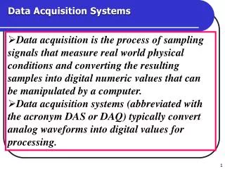
Data Acquisition Systems. ACES Presentation Brad Ellison March 11, 2003. Data Acquistion System Related Points from T. G. Guzik’s Presentation of 3/6/03 “Common PDR Problems”. How do you select an appropriate ADC? How do your sensors/transducers work? Expected Results (Mission Objectives)

E N D
Data Acquisition Systems ACES Presentation Brad Ellison March 11, 2003
Data Acquistion System Related Points from T. G. Guzik’s Presentation of 3/6/03 “Common PDR Problems” • How do you select an appropriate ADC? • How do your sensors/transducers work? • Expected Results (Mission Objectives) • Sensor/transducer selection • ADC selection • Test hardware by prototyping. • Verify software works. • Calibrations. • How to get data OUT of on-board storage? • How to get data INTO storage? • Data volume, format. • How do you test your payload?
ADC DATAQ system proposed by most PDR’s Basic Stamp Sensor • Variations in proposed sensor configuration • Multiple sensors connected to an input multiplexer • Multiple sensors connected to separate ADC’s • Multiple sensors with separate DATAQ systems,i.e, HOBO • Variations in proposed ADC digital configuration • separate Stamp I/O pins for multiple ADC’s. • shared data/clock;separate enable lines for multiple ADC’s.
PDR’s indicated some possible misconceptions or lack of understanding of sensor, ADC, Data Acquisition system design. • There are many kinds of sensors. Thermistors are not the only available temperature sensors. • Many ADC’s are available. The ADC0831 used as an examples may not always be appropriate. • Sensors do not usually connect directly to the ADC. Other circuitry may be required. • Serial ADC’s require appropriate software to generate SCL and write/read SDA lines. Software effort may be underestimated. Also to applies to reading/writing serial EEPROM’s.
Data Acquisition System Sensor Signal Conditioning MUX Software Sensor Signal Conditioning SCL ADC CPU SDA Sensor Signal Conditioning CS Storage Telemetry Display Sensor Signal Conditioning
Sensors/Transducers • Transducers sense some physical phenomena and produce an electrical signal or vary an electrical property that the data acquisition measures. • Voltage output • Current output • Variable resistance (or conductance) • Variable capacitance • ADC inputs typically are voltage sensitive. • Expected range of electrical output. • Calibrations. • Testing of sensor, ADC, software.
Signal ConditioningSensor output must be compatible with ADC input over the expected measurement range and optimized as required. • Conversion of current, resistance, etc. to a suitable voltage range by amplification or attenuation and/or level shifting. For highest accuracy the maximum range of the conditioned signal equals the maximum voltage input range of the ADC. • Filtering (noise, extraneous signals). • Isolation of sensor from computer system.
Signal Conditioning cont’d • Multiplexing of multiple sensor channels. • Excitation - Some transducers will need external voltage or current excitation signals. • Linearization - can also be done in DATAQ software or data analysis software.
Analog-to-Digital Converters (ADC)Specifications • Number of channels • Conversion time (sampling rate) • Resolution (8-bit, 12-bit, etc.) • Input Range and Span (fixed or selectable?) • Differential Non-linearity (DNL) • compared to ideal ADC • deviation from ideal response is DNL.
ADC’s cont’d • Digital interface to host CPU • Serial • Parallel • Reference Voltage • Internal • External