Download
1 / 20
200 likes | 224 Views
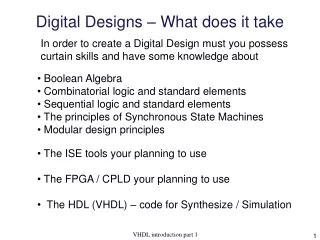
In order to create a digital design, you must possess certain skills and knowledge about boolean algebra, combinatorial logic, sequential logic, synchronous state machines, modular design principles, ISE tools, FPGA/CPLD, and VHDL code for synthesis and simulation.

E N D
Digital Designs – What does it take In order to create a Digital Design must you possess curtain skills and have some knowledge about • Boolean Algebra • Combinatorial logic and standard elements • Sequential logic and standard elements • The principles of Synchronous State Machines • Modular design principles • The ISE tools your planning to use • The FPGA / CPLD your planning to use • The HDL (VHDL) – code for Synthesize / Simulation VHDL introduction part 1
Very Hard Difficult Language VHDL V. Hardware Description Language Very high speed integrated circuit To the C programmers – forget what you learned (Well at least some of it ) VHDL introduction part 1
The Software Approach Fixed hardware in combination with flexiable software. void Count_and_compare( ) { while (button==0); // Button been pressed Counter = Counter +1;if (Counter=5) { Led = 1; Counter = 0; }else Led = 0; while (button==1); // Button now released} Software executed ina sequential manner. MachineCode Source CodeHigh Level Language 24FE5619CABE34780067 Compiler VHDL introduction part 1
Hardware Description for Synthesize The synthesize tool uses the descriptionto create to wanted hardware. Note! How the comparator reused 1 1 2 2 RTL View Note! The order of statements doesn’t matter VHDL introduction part 1
Hardware View Inside a LUT VHDL introduction part 1
Inside a Field Programable Gate Array CLB PSM LUT VHDL introduction part 1
Hardware Description for Simulation VHDL introduction part 1
The order do matter (inside a process) VHDL introduction part 1
HDL-based design flow (1) • For ASICs, verification and fitting phases are usually much longer. VHDL introduction part 1
Requirements RTL Model Simulate Synthesize Gate-levelModel Simulate Test Bench ASIC or FPGA Place & Route TimingModel Simulate HDL-based design flow (2) VHDL introduction part 1
The Xilinx ISE 11 design flow The file Hierachy The Processes to chose amongSynthesize will translate the design to Booleanequations for simulation and implementation Implement Design will perform the processes ofTranslation, Mapping and finally Place&Route Generate Programming File will create the bit-file for downloading to the FPGA / CPLD VHDL introduction part 1
VHDL • Developed in the mid-1980s under DoD sponsorship • Mandated for federally-sponsored VLSI designs • Used for design description, simulation, and synthesis • Synthesis became practical in the early 90s and use of VHDL (and Verilog) has taken off since then • Only a subset of the language can be synthesized VHDL introduction part 1
The Complete VHDL definition Code forSynthesize Code forSimulation The make the picture complete – it all depends onwhich part of VHDL the ISE offers you . VHDL introduction part 1
CodeforSimulation VHDL introduction part 1
CodeforSynthesize B C F A VHDL introduction part 1
VHDLEntity and Architecture concept • System is a collection of modules. • Architecture: detailed description of the internal structure or behavior of a module. • Entity: a “wrapper” for the architecture that exposes only its external interfaces, hiding the internal details. VHDL introduction part 1
VHDL Hierarchy VHDL introduction part 1
VHDL program file structure • Entity and Architecture definitions for different modules can be in different files. • Compiler maintains “work” library and keeps track of definitions using Entity and Architecture names. VHDL introduction part 1
VHDL programming styles • Structural • Define explicit components and the connections between them. • Textual equivalent of drawing a schematic • Dataflow • Most like Boolean -- assign expressions to signals • Includes “when” and “select” (case) statements • Behavioral • Write an algorithm that describes the circuit’s output • May not be synthesizable or may lead to a very large circuit • Primarily used for simulation VHDL introduction part 1
Now lets practice VHDL VHDL introduction part 1