Download
1 / 4
40 likes | 165 Views
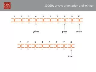
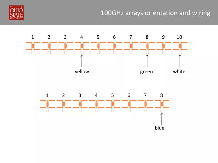
100GHz arrays orientation and wiring. 1. 2. 3. 4. 5. 6. 7. 8. 9. 10. yellow. green. white. 1. 2. 3. 4. 5. 6. 7. 8. blue. 100GHz array far field. center of array. 1. 2. 3. 4. 5. 6. 7. 8. 9. 10. angle. 47.5 o. 6 o. 6 o. 47.5 o. 38 o. 28.5 o. 17.5 o. 28.5 o.

E N D
100GHz arrays orientation and wiring 1 2 3 4 5 6 7 8 9 10 yellow green white 1 2 3 4 5 6 7 8 blue
100GHz array far field center of array 1 2 3 4 5 6 7 8 9 10 angle 47.5o 6o 6o 47.5o 38o 28.5o 17.5o 28.5o 17.5o 38o Far field pattern of the 5 (left) array elements
100GHz antennas’ characteristics • Horn antenna • (diameter=2cm (dm), length= 5.5cm (L)) Gain = 295 = 24.27 (dB) Aeff = 211.3mm2 => D = 8.2mm • Lens antenna Gain = 335.7 = 25.27 (dB) Aeff = 240.5mm2 => D = 8.75mm Including losses: Ohmic:10%, Air/dielectric interface:30% , Back (air) radiation: 9%
Different diode areas responsivity response A = 0.43 , Area = 0.31mm2 A = 0.38 , Area = 0.28mm2 Old detector (A=4.14)