Download
1 / 2
20 likes | 108 Views
Patient Specific Motion Modeling and Assistive Devices. S Russell, P Sheth, B Bennett, P Allaire, M Abel. University of Virginia, Motion Analysis and Motor Performance Laboratory, Charlottesville, VA. INTRODUCTION. METHODS (cont). RESULTS (cont). Angular Momentum Control. Foot Model

E N D
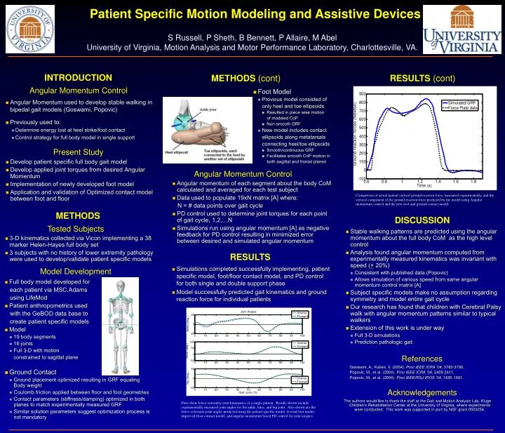
Patient Specific Motion Modeling and Assistive Devices S Russell, P Sheth, B Bennett, P Allaire, M Abel University of Virginia, Motion Analysis and Motor Performance Laboratory, Charlottesville, VA. INTRODUCTION METHODS (cont) RESULTS (cont) Angular Momentum Control • Foot Model • Previous model consisted of only heel and toe ellipsoids • Resulted in piece wise motion of modeled CoP • Non-smooth GRF • New model includes contact ellipsoids along metatarsals connecting heel/toe ellipsoids • Smooth/continuous GRF • Facilitates smooth CoP motion in both sagittal and frontal planes • Angular Momentum used to develop stable walking in bipedal gait models (Goswami, Popovic) • Previously used to: • Determine energy lost at heel strike/foot contact • Control strategy for full body model in single support Present Study • Develop patient specific full body gait model • Develop applied joint torques from desired Angular Momentum • Implementation of newly developed foot model • Application and validation of Optimized contact model between foot and floor Angular Momentum Control • Angular momentum of each segment about the body CoM calculated and averaged for each test subject • Data used to populate 19xN matrix [A] where: N = # data points over gait cycle • PD control used to determine joint torques for each point of gait cycle, 1,2,…N • Simulations run using angular momentum [A] as negative feedback for PD control resulting in minimized error between desired and simulated angular momentum Comparison of actual patient vertical ground reaction force, measured experimentally, and the vertical component of the ground reaction force predicted by the model using Angular momentum control and the new foot and ground contact model. METHODS DISCUSSION Tested Subjects • Stable walking patterns are predicted using the angular momentum about the full body CoM as the high level control • Analysis found angular momentum computed from experimentally measured kinematics was invariant with speed (+ 20%) • Consistent with published data (Popovic) • Allows simulation of various speed from same angular momentum control matrix [A] • Subject specific models make no assumption regarding symmetry and model entire gait cycle • Our research has found that children with Cerebral Palsy walk with angular momentum patterns similar to typical walkers • Extension of this work is under way • Full 3-D simulations • Prediction pathologic gait • 3-D kinematics collected via Vicon implementing a 38 marker Helen-Hayes full body set • 3 subjects with no history of lower extremity pathology were used to develop/validate patient specific models RESULTS • Simulations completed successfully implementing, patient specific model, foot/floor contact model, and PD control for both single and double support phase • Model successfully predicted gait kinematics and ground reaction force for individual patients Model Development • Full body model developed for each patient via MSC.Adams using LifeMod • Patient anthropometrics used with the GeBOD data base to create patient specific models • Model • 19 body segments • 16 joints • Full 3-D with motion constrained to sagittal plane • Ground Contact • Ground placement optimized resulting in GRF equaling Body weight • Coulomb friction applied between floor and foot geometries • Contact parameters (stiffness/damping) optimized in both planes to match experimentally measured GRF • Similar solution parameters suggest optimization process is not mandatory References Goswami, A., Kallen, V. (2004). Proc IEEE ICRA ’04, 3785-3790. Popovic, M., et al. (2004). Proc IEEE ICRA ’04, 2405-2411. Popovic, M., et al. (2004). Proc IEEE/RSJ IROS ’04, 1685-1691. Acknowledgements The authors would like to thank the staff at the Gait and Motion Analysis Lab, Kluge Children’s Rehabilitation Center at the University of Virginia, where experiments were conducted. This work was supported in part by NSF grant 0503256. Plots show lower extremity joint kinematics of a single patient. Results shown include experimentally measured joint angles for the ankle, knee, and hip joint. Also shown are the lower extremity joint angles predicted using the patient specific model, revised foot model, improved floor contact model, and angular momentum based PD control for joint torques
Upright Moment Arm Tension Adjustor Release Mechanism Hinge Cable Ratchet Mechanism Springs Moment Arm Assist Adjustors Upright Release Mechanism Hinge Cable Shoe Pulleys Sole Springs Patient Specific Motion Modeling and Assistive Devices S Russell, P Sheth, B Bennett, P Allaire, M Abel University of Virginia, Motion Analysis and Motor Performance Laboratory, Charlottesville, VA. INTRODUCTION Cerebral Palsy Present Studies • Develop plantar flexion assist ankle foot orthosis (AFO) to promote heel strike while facilitating 3 rockers of stance • Develop passive brace to store energy lost at heel strike and return it during pre swing • Develop motorized walker to predict gait events and assist subjects in walking and turning • 764,000 people in the United States have symptoms of Cerebral Palsy (CP) • Metabolic costs of walking 2-3 times higher in individuals with CP • 50% of people with CP are prescribed Ankle Foot Orthotics (AFO) • Previous research equivocal on effectiveness of AFO’s Plantar Flexion Assist AFO Energy Return AFO Smart Walker Objectives Objectives Objectives • Develop an AFO which limits plantar flexion during swing due to conditions such as equinus or drop foot • Allow patient kinematics to exploit all three rockers during stance (Figure 1) • Energy added from ankle plantar flexion at push off for CP gait typically 15-20% less than normal gait • Develop an AFO to store the energy lost during heel strike and return the energy later in gait cycle (i.e. push off) • Return .4 J/kg of energy to gait at push off (15% total normal energy added at push off) • Allow patient kinematics to exploit all three rockers during stance (Figure 1) • Preform real-time prediction of gait events (i.e. heel strike, toe off) via forces applied to walker handles • Create shared control of a motorized posterior walker to facilitate better walking in children with CP Previous Solutions Figure 1. 1st Rocker represents rotation about the heel at initial heel contact allowing the foot to lay flat, 2nd Rocker allows the body to progress forward rotating about the ankle with the foot flat in stance, and the 3rd rocker allows the subject to rotate onto the ball of there foot to facilitate push off during pre swing. • Post-processing prediction of gait events from handle forces validated using VICON motion analysis • Implementation of shared control on steering angle to control anterior walker trajectories Current AFO’s • Solid ankle AFO’s are unable to return energy to gait cycle while PLS, ground reaction, and carbon toe off AFO’s store and return energy at push off but do so by inhibiting the 2nd rocker Current AFO’s • Solid ankle AFO’s and posterior leaf spring (PLS) restrict or inhibit one or more kinematic rockers • Hinged AFO’s facilitate rockers but cannot inhibit foot drop or equinus Current Solution Design Current Solution Design • Based on a double upright AFO with dual action joints • Patient specific conical compression springs located between foot bed and sole of shoe • Ankle plantar flexion compresses the springs via the cable, moment arm, and pulleys • Spring tension is adjusted to apply patient specific plantar flexion assist during swing phase • In stance springs are compressed as weight is transferred forward releasing tension on moment arm facilitating full range of motion and all 3 rockers • Development of “real time” prediction of Gait events from forces applied to walker handles during walking • Development of shared control algorithm to control electric motors for desired walker motion • Hold walker position fixed in cases of impending fall (instability) • Interject energy during strategic gait events (push off) • Facilitate directional control of walker • Negate additional work of dragging a walker during gait • An additional benefit of the design is the energy return applied during pre swing to aid push off as the springs decompress as body weight is removed Current Solution Design • Energy stored at heel strike • Body weight compresses springs • Springs held in compression by multi-tooth ratchet system • Tension in cables released to facilitate full range of motion • Energy returned during push off • Body rotates forward over foot (2nd rocker) • Foot is dorsi-flexed taking slack out of cable • Weight in on ball of foot activating mechanism to release springs • Springs create plantar flexion moment about ankle joint via cables