Download
1 / 28
290 likes | 497 Views
Goal of this lecture. Present understanding of device operation nMOS/pMOS as switches How to design complex gates using nMOS/pMOS transistors. |V. |. GS. A Switch!. An MOS Transistor. What is a Transistor?. The MOS Transistor. Polysilicon. Aluminum. CMOS devices. The NMOS.

E N D
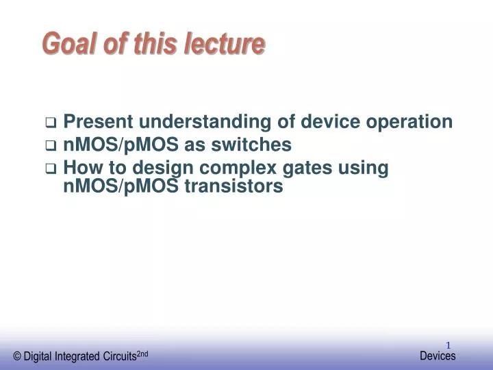
Goal of this lecture • Present understanding of device operation • nMOS/pMOS as switches • How to design complex gates using nMOS/pMOS transistors
|V | GS A Switch! An MOS Transistor What is a Transistor?
The MOS Transistor Polysilicon Aluminum
The NMOS • Substrate: lightly doped (p-) • Source and drain: heavily doped (n+) • Gate: polysilicon • Thin oxide separates the gate and the “channel” • Field oxide and field implant isolate the devices
MOS Transistors -Types and Symbols D D G G S S Depletion NMOS Enhancement NMOS D D G G B S S NMOS with PMOS Enhancement Bulk Contact
Pinch-off Transistor in Saturation
Summary of MOSFET Operating Regions • Strong Inversion VGS >VT • Linear (Resistive) VDS <VDSAT • Saturated (Constant Current) VDS VDSAT • Weak Inversion (Sub-Threshold) VGS VT • Exponential in VGS with linear VDS dependence
MOSFET equations • Cut-off region • Linear region • Saturation • Oxide capacitance/Gain Factor
-4 x 10 -4 x 10 6 2.5 5 2 4 1.5 (A) 3 (A) D D I I 1 2 0.5 1 0 0 0 0.5 1 1.5 2 2.5 0 0.5 1 1.5 2 2.5 V (V) V (V) GS GS ID versus VGS linear quadratic quadratic Long Channel Short Channel
MOS output characteristics • Linear region: Vds<Vgs-VT • Voltage controlled resistor • Saturation region: Vds>Vgs-VT • Voltage controlled current source • Curves deviate from the ideal current source behavior due to: • Channel modulation effects
At every point in time (except during the switching transients) each gate output is connected to either V or V via a low-resistive path. DD ss The outputs of the gates assumeat all timesthevalue of the Boolean function, implemented by the circuit (ignoring, once again, the transient effects during switching periods). This is in contrast to the dynamic circuit class, which relies on temporary storage of signal values on the capacitance of high impedance circuit nodes. Static CMOS Circuit
Static Complementary CMOS VDD In1 PMOS only In2 PUN … InN F(In1,In2,…InN) In1 In2 PDN … NMOS only InN PUN and PDN are dual logic networks
NMOS Transistors in Series/Parallel Connection • Transistors can be thought as a switch controlled by its gate signal • NMOS switch closes when switch control input is high
CL CL CL CL Threshold Drops VDD VDD PUN S D VDD D S 0 VDD 0 VDD - VTn VGS PDN VDD 0 VDD |VTp| VGS D S VDD S D
B A C D Complex CMOS Gate OUT = D + A • (B + C) A D B C
Cell Design • Standard Cells • General purpose logic • Can be synthesized • Same height, varying width • Datapath Cells • For regular, structured designs (arithmetic) • Includes some wiring in the cell • Fixed height and width
V DD Standard Cells N Well Cell height 12 metal tracks Metal track is approx. 3 + 3 Pitch = repetitive distance between objects Cell height is “12 pitch” Out In 2 Rails ~10 GND Cell boundary
V V DD DD Standard Cells With minimaldiffusionrouting With silicided diffusion Out In Out In GND GND
V DD Standard Cells 2-input NAND gate A B Out GND