Download
1 / 32
320 likes | 542 Views
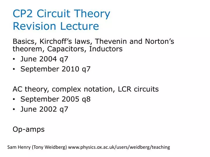
CP2 Circuit Theory Revision Lecture. Basics, Kirchoff’s laws, Thevenin and Norton’s theorem, Capacitors, Inductors June 2004 q7 September 2010 q7 AC theory, complex notation, LCR circuits September 2005 q8 June 2002 q7 Op-amps.

E N D
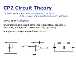
CP2 Circuit Theory Revision Lecture Basics, Kirchoff’s laws, Theveninand Norton’s theorem, Capacitors, Inductors • June 2004 q7 • September 2010 q7 AC theory, complex notation, LCR circuits • September 2005 q8 • June 2002 q7 Op-amps Sam Henry (Tony Weidberg) www.physics.ox.ac.uk/users/weidberg/teaching
+IR1 + – –V0 +IR2 + + – – +IR1 + – Kirchoff’s laws I1 I2 I1+I2–I3–I4=0 I3 I4 V0–IR1–IR2–IR3=0 R1 I R2 V0 R3
Thevenin and Norton theorem Req Veq Req In Practice, to find Veq, Req… RL (open circuit) IL0 Veq=VL RL0 (short circuit) VL0 Req = resistance between terminals when all voltages sources shorted
Capacitors Q = CV +Q C -Q Capacitors resist change in voltage • Capacitors in series • Capacitors in parallel • Stored energy stored in form of electric field C1 C2 CN
Inductors • Inductors in series • Inductors in parallel • Stored energy stored in form of magnetic field Inductors resist a change of current L “back emf” Self-inductance L1 L2
RC and RL circuits R R + + V0 V0 C L
Check Energy conservation: Total energy dissipated by resistor = Energy delivered by source
AC circuit theory • Voltage represented by complex exponential • Impedance relates current and voltage V=ZIin complex notation: Resistance R Inductance jL Capacitance 1/jCand combinations thereof • Impedance has magnitude and phase represented by real component of easily shown from Q=VC
Current is given by • So |Z| gives the ratio of magnitudes of V and I, and give the phase difference by which current lags voltage
The complex impedance is given by the voltage in a circuit divided by the current when both are expressed in complex form. The magnitude of the complex impedance is the ratio of the magnitudes of the voltage and current; the phase is the phase lag between the voltage and current.
An oscillating voltage of frequency ω, V(t)=V0cos(ωt) is represented in complex notation by V0ejωt. The current in the circuit is then given by I=V/Z, where Z is the complex impedance Z=|Z|ejφ, where |Z| is the ratio of the magnitude of the voltage to the magnitude of the current, and φ is the phase by which the current leads the voltage. The real component of Z is the resistance, and the imaginary component is the reactance where C the capacitance and L is the inductance of the circuit. Complex impedances allow circuits when inductance and capacitance to be analysed using linear circuit theory in the same way as resistance
The sum of these peak voltages is not equal to V0 as VR, VC and VL all have different phases. When the complex voltages are summed VR+VC+VL=V0
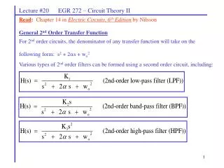
LCR circuit + L R V0 C I(t) overdamped solution critically damped solution underdamped (oscillatory) solution
Inverting Amplifier Circuit R2 i R1 v– v+ VIN VIN VOUT – i VOUT v+ v– + R1 R2 Non-Inverting Amplifier Circuit + – Gain is very large (A) Inputs draw no current (ZIN=) Feedback v+=v– Op-amps