Download
1 / 35
350 likes | 422 Views
MRD Status – Drivers 1, 2. Mechanical / ACS Recent dynamic simulations have shown that the following requirements are not valid / not met with the current mass properties

E N D
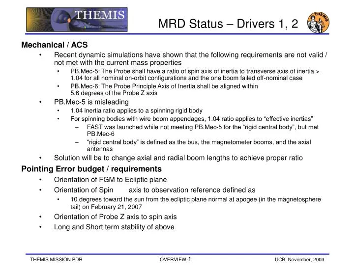
MRD Status – Drivers 1, 2 • Mechanical / ACS • Recent dynamic simulations have shown that the following requirements are not valid / not met with the current mass properties • PB.Mec-5: The Probe shall have a ratio of spin axis of inertia to transverse axis of inertia > 1.04 for all nominal on-orbit configurations and the one boom failed off-nominal case • PB.Mec-6: The Probe Principle Axis of Inertia shall be aligned within 5.6 degrees of the Probe Z axis • PB.Mec-5 is misleading • 1.04 inertia ratio applies to a spinning rigid body • For spinning bodies with wire boom appendages, 1.04 ratio applies to “effective inertias” • FAST was launched while not meeting PB.Mec-5 for the “rigid central body”, but met PB.Mec-6 • “rigid central body” is defined as the bus, the magnetometer booms, and the axial antennas • Solution will be to change axial and radial boom lengths to achieve proper ratio • Pointing Error budget / requirements • Orientation of FGM to Ecliptic plane • Orientation of Spin axis to observation reference defined as • 10 degrees toward the sun from the ecliptic plane normal at apogee (in the magnetosphere tail) on February 21, 2007 • Orientation of Probe Z axis to spin axis • Long and Short term stability of above
MRD Status – Drivers 3 - 6 • Timing Error requirements • Many requirements in the IDPU, C&DH, and Ground subsystems • Compiling end-to-end budget for all components in the path • ESC / Magnetic specifications • Working with UCB and UCLA, updates in progress • Using Magnetics and ESC Control Plans as basis for requirements • Integrated design process between Swales, UCB, and UCLA reviewing / discussing design vs. requirements • Driving Solar Cell arrangement and wiring, parts selection, grounding • Separation requirements • Deploy 5 probes from Probe Carrier without any re-contacts • Probe to Probe • Probe to Probe Carrier • Higher than normal lateral load during deployment due to need for spin stabilization • 3 Hour Eclipse / Launch • Highly elliptical orbits in / near the ecliptic plane result in long eclipses • Three hour eclipse requirement based on design compromise between bus survivability and operational constraints • Worst-case launch scenario and duration prior to achieving power-positive attitude is an Unknown at this time • Trading nominal orientation hot case with three hour eclipse is a design driver
Requirement Verification • All requirement verifications are controlled through the MRD • Functional/performance requirements verification method and documentation are data fields in the MRD • I, A, D, T, indicate Inspection, Analysis, Demonstration, or Test • The documentation column contains placeholders for how the verification will be documented • ICDs contain their own verification matrices • The Verification and Environmental Test Specification contains an Environmental verification matrix • All I&T plans will include resources for completing the verification activities