Download
1 / 25
270 likes | 562 Views
High Performance MALDI-TOF Mass Spectrometry. Marvin Vestal and Kevin Hayden Virgin Instruments Corp. Sudbury, MA. Outline. Goals: Design and build MALD-TOF Analyzers Optimized for Selected Applications Approach: Modular construction using common elements

E N D
High Performance MALDI-TOF Mass Spectrometry Marvin Vestal and Kevin Hayden Virgin Instruments Corp. Sudbury, MA
Outline • Goals: Design and build MALD-TOF Analyzers Optimized for Selected Applications • Approach: • Modular construction using common elements • State-of-the-art technology, e.g. 5 khz laser • Focus on the needs of the application • Keep it small, simple, and reliable without sacrificing performance • Analyzer geometries • Linear for broad mass range and sensitivity at high mass (to 500 kDa). • Reflector for high resolution, mass accuracy, and sensitivity at low mass (0.1-5 kDa) • Reversed geometry reflector for both resolution and sensitivity in intermediate mass range (1-50 kDa) • Optimization Strategy • Results
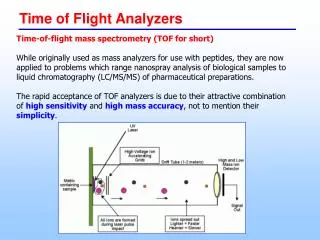
Time-of-flight analyzer geometries Ion Source Drift Tube Detector Linear Reflector Reflecting Reversed Geometry Reflecting Reflectors
Reflector MS for MALDI mass fingerprinting peptides, metabolites, and other small molecules • High sensitivity and dynamic range in mass range 0.1-5 kDa • Highest possible resolving power and mass accuracy (1 ppm RMS) • High throughput • Low cost, stable, reliable, and small • No operator expertise required
y=V/(V-V1) Ds= 2d0y3/2 Dv =Ds +(2d0y)2/(vnDt) Where vn =(2zV/m)1/2 and Dt is time lag Sample Plate V Extraction Electrode V1 Velocity focus Space focus 0 Ds d0 d1 Dv Wiley and McLaren RSI (1955) 26, 1150-1157 Vestal and Juhasz JASMS (1998) 9, 892-911 For single field source, V1=0, y=1 Simultaneous 1st and 2nd order focus Dv=6d0, vnDt=d0
Sample plate V2 V 2-stage reflector V1 velocity focus Extraction electrode Drift tube 0 Dm d4 d40 D d3 d0 Dm1 = 4d4w3/2 +4d3[w/(w-1)][1-w1/2] 3Dm2 = 4d4w5/2 +4d3[w/(w-1)][1-w3/2] d4 = d40(V-V1)/(V2-V1) w=V/(V-V1) Simultaneous 1st and 2nd order focus 4d3/Dm=(w-3)/w 4d4/Dm = w-3/2 + (4d3/Dm)/(w + w1/2)
Contributions to relative peak width, Dm/m, with 1st and 2nd order velocity focusing Initial position, dx: Rs1 = 2[(Dv-Ds)/2d0y](dx/De) Initial velocity, dv0: Rv1 =(4d0y/De)(dv0/vn)[(1-(m/m*)1/2] Rv2 =2[2d0y/(Dv-Ds)]2 (dv0/vn)2=0 Rv3 =2[2d0y/(Dv-Ds)]3 (dv0/vn)3 Rv = Rv1 + Rv3 Time error, dt: Rt = 2dt/t = 2dtvn/De Trajectory error, dL: RL = 2dL/De Voltage error, dV: RV = dV/V Resolving power: R-1 = [Rs12 + Rv2 + Rt2 + RL2 + RV2]-1/2
Instrument Parameters for Reflecting Analyzer (single-field source and two-field mirror) De=3200, d0=3, D=2264, d3=114.2, d40=127.7 all in mm V=8.56, V1=6.31, V2=9.23 all in kV dt=1.5 nsec (0.5 nsec bins, 1 nsec single ion pulse width) Focus mass m*=1.6 kDa Dv=6d0 = 18 mm, vn (for m*)=0.03215 mm/nsec Time lag Dt=d0/vn = 93 nsec K=2d0/(Dv-Ds)=0.5 Initial Conditions for MALDI (typical) dv0=400 m/sec, dx=0.01 mm Trajectory error and voltage error assumed to be small
III I II Calculated resolving power for reflecting analyzer. dv0=400m/s, dx=0.01 mm for I and III and 800 m/s and 0.02 mm for II. dt=1.5 nsec for I and II and 0.75 nsec for III,
Conditions for minimizing relative peak width, Dm/m Initial position, dx: Rs1 = 2K-1(dx/De) Initial velocity, dv0: Rv1 =(4d0y/De)(dv0/vn)[(1-(m/m*)1/2] Rv3 =2K3 (dv0/vn)3 Rv = Rv1 + Rv3 Time error, dt: Rt = 2dt/t = 2dtvn/De Peak Width: R= [Rs12 + Rv2 + Rt2 + RL2 + RV2]1/2 Optimum focus: dR/dK =0, K=2d0/Dv-Ds Optimum velocity: dR/dvn=0, vn=C(V/m*)1/2 (can be optimized at m* or any other mass)
nominal optimum R Rs1 Rv3 K=2d0/(Dv-Ds) Minimum peak width as function of focusing parameter K. Optimum value corresponds to dR/dK=0
dt=1.5 dt=0.75 Rt Rv3+ Minimum peak width as function of V/m*(indicated by arrows for dt= 1.5 and 0.75 nsec). For m*= 1600 Da optimum voltages are 2.4 and 3.4 kV, respectively.
IV III II I Optimized resolving power for reflecting analyzer, dv0=400m/s, dx=0.01 mm. dt=1.5 nsec for I and II and 0.75 nsec for III and IV. Red lines nominal, black at optimum for focus mass.
BSA digest 13,000 11,600 Resolution is 40% of calculated
Experimental resolving power for reflecting analyzer on BSA digest
Contributions to relative peak width, Dm/m Initial position, dx: Rs1 = [(Dv-Ds)/De](dx/d0y) Initial velocity, dv0: Rv1 =(4d0y/De)(dv0/vn)[(1-(m/m*)1/2] Rv2 =2[2d0y/(Dv-Ds)]2 (dv0/vn)2 Rv3 =2[2d0y/(Dv-Ds)]3 (dv0/vn)3 Time error, dt: Rt = 2dt/t = 2dtvn/De Trajectory error, dL: RL = 2dL/De Voltage error, dV: RV = dV/V Resolving power: R-1 = [Rs12 + Rv2 + Rt2+ RL2 + RV2]-1/2 Not small!!!
III I II Calculated resolving power for reflecting analyzer with dV/V =70 ppm
calculated Comparison of calculated resolving power with experimental results With dV/V=70 ppm
Calculated dt=0.75 nsec Calculated dt=0.75 nsec Comparison of calculated resolving power with experimental results With dV/V=70 ppm. Measured 5 mchannel plate ETP MagnetTOFTM
Contributions to relative peak width, Dm/m, with 1st and 2nd order velocity focusing (size matters) Initial position, dx: Rs1 = 2[(Dv-Ds)/2d0y](dx/De) Initial velocity, dv0: Rv1 =(4d0y/De)(dv0/vn)[(1-(m/m*)1/2] Rv2 =2[2d0y/(Dv-Ds)]2 (dv0/vn)2=0 Rv3 =2[2d0y/(Dv-Ds)]3 (dv0/vn)3 Time error, dt: Rt = 2dt/t = 2dtvn/De Trajectory error, dL: RL = 2dL/De Voltage error, dV: RV = dV/V Resolving power: R-1 = [Rs12 + Rv2 + Rt2 + RL2 + RV2]-1/2
De=3.2 m 10.4 6.2 De=6.4 m Rv3 K=2d0/(Dv-Ds) Minimum peak width as function of focusing parameter K for effective Lengths of 3.2 and 6.4 m. Optimum values correspond to dR/dK=0, And is proportional to De0.84 for these initial conditions.
dt=0.75 nsec dt=1.5 nsec Current instrument Calculated maximum resolving power as function of effective length neglecting voltage error.
dt=0.75 nsec dt=1.5 nsec (m) Calculated maximum resolving power as function of effective length neglecting voltage error.
Conclusions • Resolving power of prototype reflecting analyzer is limited by voltage error or trajectory error • If the total contribution of these two mass independent errors can be reduced to <10 ppm, then maximum resolving power of 50,000 is feasible with current prototype. • Maximum resolving power is proportional to De0.84 • 1,000,000 resolving power is theoretically feasible with an effective length of 100 m (physical length about 40 m) • But!!! • Errors independent of length must be less than 0.5 ppm (5 millivolts at 10 kilovolts)