Download
1 / 20
210 likes | 330 Views
Improving LIGO’s stability and sensitivity: commissioning examples. August 24, 2004 Michael Landry LIGO Hanford Observatory. Recent commissioning efforts. Reliability & Stability Seismic retrofit at LLO: Hydraulic External Pre-Isolator (HEPI) Sensitivity

E N D
Improving LIGO’s stability and sensitivity: commissioning examples August 24, 2004 Michael Landry LIGO Hanford Observatory
Recent commissioning efforts • Reliability & Stability • Seismic retrofit at LLO: Hydraulic External Pre-Isolator (HEPI) • Sensitivity • Operate at high power: achieve designed optical gain • Laser power increase • Thermal compensation system (TCS) LIGO I
RMS motion in 1-3 Hz band night Livingston day Displacement (m) Hanford PRE-ISOLATOR REQUIREMENT(95% of the time) Daily Variability of Seismic Noise LIGO I
HEPI summary • Remaining tasks • Complete commissioning of final six chambers • Sensor and whitening filter optimization • Scripting, safeties, man-machine interface software • Summary • All hardware installed • Crucial one-arm test completed successfully • LIGO will soon have two sites capable of night and day operation with reasonable duty cycle • Pre-Isolator is first Advanced LIGO subsystem shown to work at required specification at observatory setting LIGO I
LHO 4k noise history (science design) LIGO I
S1 Noise Component Analysis, LLO 4k S1 LIGO I 5 G020482-00-D Rana Adhikari noise analysis
Estimated Noise Limits for S2(as planned in October 2002) S1 S2 (expected) LIGO I
LHO 4k noise history (science design) S1 S2 S3 LIGO I
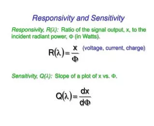
What is shot noise? • Laser light comes in discrete packets of photons • Stastical fluctuation in detected photons appears as length noise in an interferometer; Poisson statistics of light arrival times at the gravity-wave port photodiodes • Strain noise decreases with the square-root of laser power LIGO I
What can we do about shot noise? • Increase laser power • Lasers refurbishing, now running at ~8W • Approximately 4W incident on interferometers • Input optics-train modified and aligned for better throughput • Additional photodiodes added to gravity-wave port • Additional power produces “thermal lensing” in interferometer optics • necessitates Thermal Compensation System (TCS) • Ensure other high-frequency noise sources are reduced accordingly • E.g. “oscillator phase noise” LIGO I
ITM ? Thermal CompensationSystem (TCS) CO2 Laser ZnSe Viewport Over-heat pattern Inner radius = 4cm Outer radius =11cm Over-heat Correction Under-heat Correction Inhomogeneous Correction • Require TCS to match input beam to the mode supported in arm cavities • All systems installed LIGO I
Two CO2 lasers installed on H1 To input test mass (ITM) High Reflectivity surface LIGO I
TCS on the power recycled Michelson: beam images at gravity-wave port No Heating 30 mW 60 mW 90 mW Best match 120 mW 150 mW 180 mW Input beam LIGO I
High-frequency noise improvements • Recent high-frequency noise improvement by factor of 2-4 • Thermal compensation required to support this gain in sensitivity (otherwise thermal lensing would limit such gains) LIGO I
Parallel efforts • Many other key commissioning efforts underway, including • Control of angular degrees-of-freedom (d.o.f.) • All 14 angular d.o.f. controlled on Hanford 4km interferometer • Input pointing into the interferometers controlled • Acoustic mitigation • Reducing control noise from other feedback systems in the interferometers LIGO I
Time Line 2000 2004 2003 2001 1999 2002 3Q 1Q 3Q 1Q 4Q 1Q 1Q 2Q 3Q 3Q 2Q 2Q 4Q 4Q 3Q 2Q 4Q 1Q 3Q 4Q 2Q 4Q First Lock Full Lock all IFO Inauguration Now Engineering E1 E2 E7 E3 E4 E5 E6 E9 E8 Runs S3 S1 S2 S4 (expected) Science First Science Data LIGO I
Looking ahead • Livingston 4km interferometer: • Finish Hydraulic external pre-Isolator (HEPI) • Get good spectrum back • Implement improvements from LHO 4km interferometer • Hanford 4km interferometer: • High power operations • “output mode cleaner” test version 2 • New frequency and intensity stablization, “common mode” boards, non-resonant sideband photodiodes on interferometer reflected output port • Optimize dewhitening for new low-noise digital-to-analog converters • Hanford 2km interferometer: • Implement improvements from the Hanford 4km interferometer • Expect 4-6 week science run beginning Jan 2005 • On track to reach design sensitivity and begin an extended science run summer 2005 LIGO I