Download
1 / 25
270 likes | 556 Views
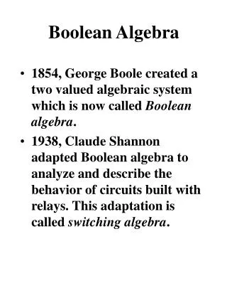
Boolean algebra. INTRODUCTION LOGICAL OPERATIONS TRUTH TABLE AND RULES. INTRODUCTION. 1854: Logical algebra was published by George Boole known today as “Boolean Algebra” It’s a convenient way and systematic way of expressing and analyzing the operation of logic circuits.

E N D
Boolean algebra INTRODUCTION LOGICAL OPERATIONS TRUTH TABLE AND RULES
INTRODUCTION • 1854: Logical algebra was published by George Boole known today as “Boolean Algebra” • It’s a convenient way and systematic way of expressing and analyzing the operation of logic circuits. • 1938: Claude Shannon was the first to apply Boole’s work to the analysis and design of logic circuits.
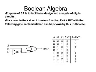
TRUTH TABLE • A TRUTH TABLE is a table which represents all the possible values of logical variables along with all possible results of the given combination of values
Logical operators/GATE • NOT operator/GATE • OR operator/GATE • AND operator/GATE
NOT OPERATOR/GATE • This operator operates on single variable. • Operation performed by the NOT operator is called complementation. • The symbol for NOT operator is represented by “~”. • Thus X means complement of X.
Truth table for not operator/GATE • Assume only one of the two values 0 and 1. • Where 0 denotes false value • And 1 denotes true value
Table X X 1 0 1 0
VENN DIAGRAM x x
OR OPERATOR/GATE • This operator denotes operation called logical addition. • The symbol is represented by “+”. • Thus X+Y can be read as X OR Y. • For OR operation the possible input and output combinations are as follows.
table 0 + 0 = 0 0 + 1 = 1 1 + 0 = 1 1 + 1 = 1
AND OPERATOR/Gate • AND operator performs another important operation of boolean algebra calleid logical multiplication. • The symbol for AND operation “(.)” dot. • Thus X.Y is read as X AND Y.
The rules for and 0 . 0 = 0 0 . 1 = 0 1 . 1 = 1 1 . 0 = 0
BOOLEAN ALGEBRA RULES • Properties of 0 :- 0+0=0; 0.X=0 • Properties of 1:- 1+X=1; 1.X=X • Indempotence law:- • X +X = X
rules • X . X = X • Involution • X = X • Complementary law • X + X = 1 • X . X = 0
tHANKS MONICA J CLASS XII –A(2012-13) COMPUTER SCIENCE