Download
1 / 71
740 likes | 1.02k Views
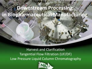
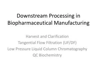
BIOMAN 2011 CHO- tPA Production System Downstream Processing. Mike Fino MiraCosta College. Unit Operations. Many decisions to be made at each step in the process. Downstream Example. Harvest Separation (Clarification).

E N D
BIOMAN 2011CHO-tPA Production SystemDownstream Processing Mike Fino MiraCosta College
Unit Operations Many decisions to be made at each step in the process
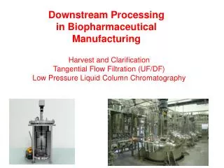
Harvest Separation (Clarification) • There are two technologies for removing the cell mass from the solution containing the target protein prior to loading onto columns: • Centrifugation (e.g. disk stack) • Filtration • Dead-ended filtration(aka normal flow: membrane + depth) • Crossflow membrane filtration(aka tangential flow) • Crossflow membranes are preferred for large scale operations and have many advantages
Media and Cells In, Clarified Media Out CLARIFIED BROTH SLUDGE
NORMAL FLOW FILTRATION (NFF): Traps contaminants larger than the pore size on the top surface of the membrane. Contaminants smaller than the specified pore size pass through the membrane. Used for critical applications such as sterilizing and final filtration. MEMBRANE DEPTH
Sterilizing Filters:Industry/Regulatory standard • Capable of achieving an LRV >7 for a B. diminuta challenge using ASTM methodology (per FDA Guidelines) • > 7 LRV means <1 microbe / 107 microbe challenge • Doesn’t specify pore size or filter type • B. diminuta model organism • Sterilizing filters must be able to retain all challenge microorganisms at a maximum bioburden
Tangential Flow Filtration Clarification/Purification Concentration Buffer Exchange Uses Crossflow to reduce build up of retained components on the membrane surface Allows filtration of high fouling streams or high resolution
Integral Membrane Non-Integral Membrane Contaminants larger than pores upstream Contaminants larger than expected pores upstream Downstream contamination No downstream contamination What is Membrane Integrity?
A benefit of membrane filters is the ability to perform a non-destructive integrity test. • Testing ensures filtration SYSTEM integrity before, during, or after filtration. • Membrane prefilters and depth filters cannot be integrity tested with precision or accuracy because of wide pore distribution. Principles of Integrity Testing
Confirms manufacturers specifications • Assures integrity after steaming or autoclaving • Assures integrity before sterilization • Detects system leaks due to o-rings, gaskets, faulty seals • Assures the correct pore size filter • Part of corporate standard operating procedure • GMP requirement • Audit requirement Reasons to Integrity Test
Destructive • Provided as a manufacturers assurance of microbial retention. • Bacterial Challenge • Non-Destructive • Provided to allow in-situ testing • Pressure hold • Bubble Point • Diffusion Two Basic Types of Integrity Test
Saline lactose media w/ B. Diminuta Test Filter 0.22 or 0.1 m disc or filter cartridge Assay Filter (47mm MEC disc) 47mm disc on TSA MEC = mixed esters of cellulose TSA = tryptic soy agar Basic Elements of a Bacterial Retention Test
Water held with surface tension Open pore space View of the membrane cross-section • Fully wetted membrane filters hold liquid in their pores by surface tension and capillary forces. • Bubble point pressure is inversely related to largest pore diameter Non-Destructive Integrity Test Bubble Point
Water Wet Integral Membrane Water Wet Non-Integral Membrane Air pressure upstream less than specification Air pressure upstream greater than specification psi psi Water in pores is a barrier to gas flow: No gas flow observed downstream until upstream pressure exceeds critical value Gas will flow through large opening and is easily observed downstream What is Pressure Hold/Bubble Point?
Inverse Relationship:Pore size v. Bubble Point • A sterilizing filter has a log reduction value of greater than 7 Decreasing pore size
Retentate Flow Outlet Pressure Permeate Flow Hollow Fiber Feed Flow Inlet Pressure
PERISTALTIC PUMP: Creates a gentle squeezing action to move fluid through flexible tubing.
initial feed diafiltrate retentate reservoir feed filter product feed recovery pump Introduction: TFF Layout & Operation permeate • Operating Steps: • Flush • Clean Water Flux • Pump curve • Integrity Test • Buffer Flush • Microfilter • Or Concentrate • OrDiafilter
Key Parameters • Feed Flow rate • Flow rate leaving the pump • Set by pump speed • Transmembrane pressure (TMP) • Average of inlet/outlet pressures • Set by backpressure (retentate) • Permeate control • Flow rate through the fibers • Set by backpressure (permeate) • We don’t use this control in this cllass • Membrane area • Scales linearly
Transmembrane Pressure (TMP) InletFeed Pressure RetentatePressure • TMP = (Pin + Pout)/2 - Pperm Pin = 30psi Pout = 20psi We leave this line unrestricted Permeate Pressure Filter membrane Pperm = 0psi TMP = (30 + 20)/2 - 0 = 25 PSI
System Operation Initial Feed Diafiltration Buffer Steps • Clean water flux • Pump Curve • Integrity Test • Filtration Flush Retentate Tank Pump Membrane Feed Permeate
Operation: Microfiltration Trash Collect and Keep
Operation: Microfiltration Trash Collect and Keep
Operation: Microfiltration Trash Collect and Keep
Operation: Microfiltration Trash Collect and Keep
Operation: Microfiltration Trash Collect and Keep
Operation: Microfiltration Trash Collect and Keep
Initial Feed Diafiltration Buffer Flush Retentate Tank Pump Membrane Feed Permeate Operation: Concentration • Dewater the retained solutes • Procedures • Fill tank with process fluid • Start pump and adjust system to recommended flows/pressures • Remove permeate
Initial Feed Diafiltration Buffer Flush Retentate Tank Pump Membrane Feed Permeate Operation: Diafiltration • “Wash out” permeable solutes- product or contaminants • Procedure: • Add diafiltration buffer to the feed tank at the same rate that permeate is being removed from the system