Download
1 / 5
50 likes | 239 Views
Check out the pdf file for making safe waves in hazardous areas. Visit website http://www.extech.co.za/ for more information.

E N D
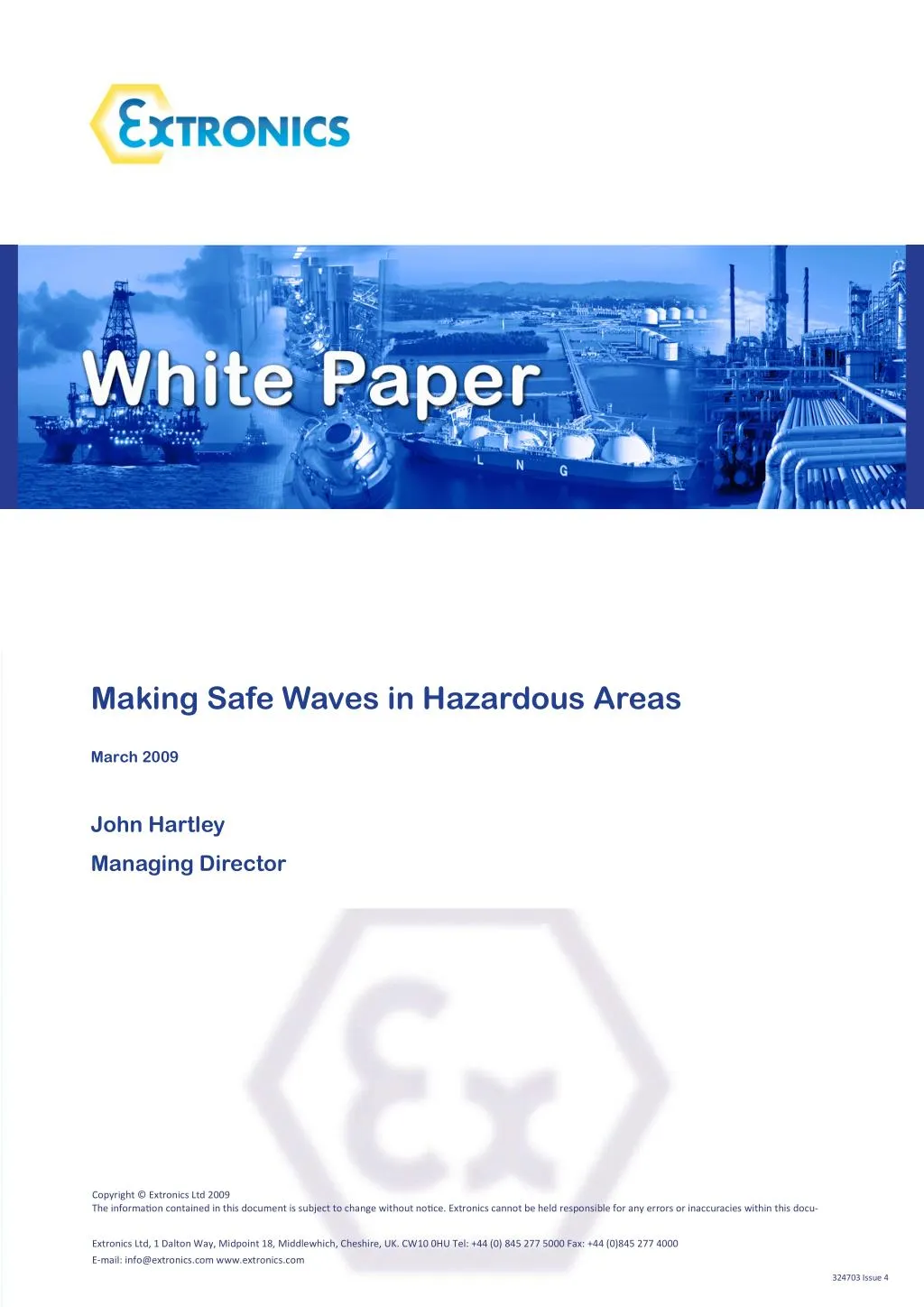
Making Safe Waves in Hazardous Areas March 2009 John Hartley Managing Director Copyright © Extronics Ltd 2009 The informa?on contained in this document is subject to change without no?ce. Extronics cannot be held responsible for any errors or inaccuracies within this docu- Extronics Ltd, 1 Dalton Way, Midpoint 18, Middlewhich, Cheshire, UK. CW10 0HU Tel: +44 (0) 845 277 5000 Fax: +44 (0)845 277 4000 E-mail: info@extronics.com www.extronics.com 324703 Issue 4
Extronics Ltd | Making Safe Waves in Hazardous Areas! Making Safe Waves in Hazardous Areas! As wireless devices such as mobile phones and laptop computers become more reliable and cost effec?ve, there is growing interest amongst the process industry as to the benefits to be found from enabling such devices to be used in hazardous areas. However, unlike most industries this is not a simple task. Installing wireless networks in hazardous areas requires careful, expert planning and execu?on. John Hartley, Managing Director of Extronics, explains the hazards posed by radio frequency sources and the issues involved when installing wireless networks in hazardous areas, and how to minimise the poten?al risk. We’ve been using radio waves in both the business and consumer worlds for a long ?me, but it is only in the last decade or so that radio devices have become more prevalent in the process industries. Portable radios and pager devices were the first devices to gain cer?fica?on for use in hazardous areas, a=er they had been tried and tested in the wider business world. The radio frequency spectrum covers a wide range from radio waves to gamma rays but the agreed area of RF under the explosion protec?on standards only covers the range from 10KHz to 300GHz and that is where this ar?cle will focus. It has always been understood that radio frequency (RF) can cause igni?on in the right set of circumstances, but when the early radios and pagers were first introduced to the process plants, there was liAle informa?on or guidance in the Explosion Protected (Ex)- type approval standards to clarify what was a safe amount of RF power to be allowed in the different types of hazardous area. The earliest research into this maAer came about more than 30 years ago when the UK Government was proposing to build new petrochemical facili?es near to exis?ng TV and radio transmiAer networks and those in opposi?on to the schemes objected on the basis that these installa?ons would be dangerous due to the risk of inadvertent igni?on by the radio frequency transmissions. Because of the strategic nature of these facili?es and their importance to the UK economy a large amount of research and tes?ng was undertaken and the resultant findings proved what the acceptable safe limits of RF were. It is only in more recent ?mes, as interest is gathering in RF devices and networks, that this informa?on has been more widely circulated and published and acceptable explosion protec?on techniques sanc?oned. There are now a number of approval standards that must be adhered to, including the BS 6656:2002, EN60079 series and IEC60079-0 which we will refer to in this ar?cle. The standard ‘BS 6656:2002’ explains the methods that can be used to assess if an RF installa?on is safe to operate in a hazardous area. It details methods and principles to assess installa?ons that are above the safe RF power limits and if they present a hazard due them ac?ng as an antenna and possible source of spark igni?on. The final dra= of ‘IEC60079-0 Ed 5.0’ provides radio frequency power or energy threshold tables (table 4 and 5), which can be used to determine if equipment will be safe for use within hazardous areas. Many people don’t even realise that RF is a hazard. We have had customers ask “why do we need a cer?fied antenna when it is only fed with RF?” This common misconcep?on is understandable, as there are s?ll very few cer?fied wireless devices on the market and they are only just star?ng to appear under relevant standards. There are a number of ways radio frequency can be a poten?al hazard in explosive atmospheres. We know that radio waves and microwaves induce currents in metallic structures such as cranes, pipes and vessels, which can cause sparking if there is a gap in the structure. The power dissipated in the spark may be sufficient to ignite a flammable atmosphere if the radio wave is strong enough. For some applica?ons, such as pulsed radio transmissions in radar, the amount of power may be higher than these levels, but only for a rela?vely short amount of ?me. It is possible in these circumstances to use another limit, based on threshold energy. Where the pulse ?me is less than half the thermal ini?a?on ?me, and the interval between pulses is longer than the thermal ini?a?on ?me, the above men?oned EN60097-0 table can be referred to establish the safety of the device. Figure 1. Radio frequency Ex power levels table 4 Figure 2. Radio frequency Ex power levels table 5 ExtronicsTel: +44 (0) 845 277 5000 | www.extronics.com 2
Making Safe Waves in Hazardous Areas! | Extronics Ltd Fortunately, much of the wireless technology we deal with has RF power levels lower than the 2W limit, which means it can be used in a hazardous area without restric?ons. However, when the amount of power is above the safe levels then the BN 6656 can be used to assess the installa?on for safe use in hazardous areas. The most obvious, but not necessarily the most prac?cal solu?on for a safe installa?on is to ensure the antenna is placed a safe distance outside of the hazardous area so that the level of RF power is below the safe limit before it enters the hazardous area. It is also possible to cer?fy specific devices for use only within a safe distance from metallic structures and structures or equipment such as cranes, columns, pipes and tanker loading sta?ons, which can act as antenna and thus pose as a sparking hazard. The issue with this approach though is ensuring that the condi?ons subsequently remain the same as when the assessment was carried out. Gas detectors can be employed to monitor the unsafe perimeters around an antenna and cer?fy the system for use to reduce the level of hazardous area the equipment is installed in. Should a hazardous area be detected the power is isolated from the equipment, thus rendering it safe. We would only recommend this approach for lower risk areas such as Zone 2. The main hazard to be found with wireless networks is associated with the electrical hazard from the RF output stage. The hazard posed by electrical equipment has been catered for over many decades with the earliest standards and protec?on concepts now over 50 years old. The two key hazards are the risk of a spark when a device short circuits due to inadequate creepage and clearances or from a foreign body entering a piece of equipment. Igni?on can also be caused by the hea?ng effect of components conduc?ng electrical current which are not adequately power rated. Also a non baAery powered radio transceiver is ul?mately connected to mains voltage and thus under fault condi?ons this voltage could be transferred through to an antenna and if that antenna does not have suitable creepage and clearance or be of a suitably robust construc?on it could cause an incendive spark or become dangerously hot. This means that either the RF stage has to have an intrinsically safe output or antennas must meet a range of stringent mechanical, construc?onal and thermal requirements to ensure that the installa?on is safe should any of the above events occur. Many of the earlier deployments of 802.11 WLAN access points used antennas poin?ng through ‘Ex d enclosure windows’ (flameproof, sealed enclosures with a toughened glass window for reading dials or, in this case, transmiRng data). Some s?ll do today. This is quite suitable for applica?ons at lower frequencies but not ideal for higher frequencies such as 2.4 and 5GHz WLAN as the glass aAenuates a high propor?on of the signal and with only 100mW max power permiAed from the transceiver in the case of an 802.11b/g WLAN it is not the best solu?on. Another issue with this method is that the access point only directs RF power from the front of the enclosure (not in the case of glass dome Ex d enclosures), which will limit the flexibility of the device and also cause RF shadows in the close proximity of the unit. RF mul?-path interference can also be created at higher frequencies which is an effect one seeks to avoid in deployments. However, although this method has its failings, it is cost effec?ve and the Ex cer?fica?on is very simple, so it does have its place! If the antenna complies with the EN60079-0 general requirements and specific sub-categories, such as Ex d flame proofing EN60079-1, Ex e increased safety EN60079-7 or Ex m device encapsula?on EN60079-18, the only other area requiring assessment by the installer is the maximum power output of the RF stage. This is because the antenna will have been designed and cer?fied to be safe under fault condi?ons in a hazardous area, for instance a 250VAC mains fault being transferred into the antenna by the RF stage of the transceiver. The only issue regarding these specially designed and Ex approved antennas is that currently there are only omni direc?onal types available and they are very expensive compared with standard industrial antennas due to the fact they are made in low volumes and constructed from special materials. The best solu?on to minimise costs and widen the range of antenna’s in hazardous areas is to find a way of using standard industrial antennas. This is possible if the output of the RF transceiver is intrinsically safe, Ex i in accordance with EN60079-11. Figure 3. Antenna in Ex’d enclosure with window Figure 4. iANT100 Antenna ExtronicsTel: +44 (0) 845 277 5000 | www.extronics.com 3
Extronics Ltd | Making Safe Waves in Hazardous Areas! The classic ‘zener barrier’ (a safety barrier consis?ng of a current limiter circuit, a voltage limiter circuit and a fuse for voltage limiter circuit protec?on) is the simplest solu?on to making the transceiver RF stage intrinsically safe, as it will prevent any possible faults in the transceiver being propagated or transferred to the hazardous area. Any fault current up to a value of 250 VAC will be absorbed by the zener diodes and very quickly the fuse will blow, turning off the power to the hazardous area. However nothing is ever that simple. Although the RF output stage may have been made intrinsically safe, the constraints of the zener barrier’s capabili?es (various reasons but the key components in currently available devices are not of an RF grade design) means that this principle can only be used on lower frequency signals, typically less than 500KHz, as the signal aAenua?on and distor?on effec?vely renders the signal useless. The easiest way to block low frequency mains faults is to use Figure 5. Zener barrier series coupled capacitors as these block all low frequency signals but not all faults so they also require a current limi?ng resistor to protect against transient faults (EN60079-11 clause 8.5 Blocking Capacitors - s?pulates that when used between intrinsically safe circuits and non intrinsically safe circuits - All possible transients shall be taken into account, and the effect of the highest nominal opera?ng frequency (as that supplied by the manufacturer) in that part of the circuit shall be considered.) However although this type of circuit is a bone fide technique it must be assessed along with the transceiver electronics to make sure other faults such as the MHz range cannot pass through the circuit incendively. Currently the only prac?cal way to make an RF stage intrinsically safe is to design the modifica?ons into the equipment in the ini?al development phase and take it through no?fied body cer?fica?on. For zone 2 applica?ons the protec?on of the transceiver RF stage is much easier due to the fact that fault condi?ons are not considered. The point being made here is that for Zone 0 and Zone 1applica?ons there is currently no off the shelf RF intrinsically safe barrier that can just be inserted into a circuit Figure 6. High frequency RF barrier and applied to an RF output stage like it were a 4.20mA or 24 VDC signal without it being further considered by a no?fied body and a type approval issued. Also, the antenna gain must not be forgoAen when assessing if the RF transceiver is suitable for use in a hazardous area. A calcula?on of the maximum EIRP (Effec?ve Isotropic Radiated Power) must be made to ensure the power radia?ng from the antenna is below the limits for the relevant hazardous area. In this example of a long distance link it is easy to see how the RF output stage is intrinsically safe and way below the 2W limit. But once a high gain antenna is connected, it is massively over the limit and would become an incendiary in any hazardous area. It is not just a maAer of making the network and devices safe and compliant with regula?ons. It also has to work! Any wireless point-to-point or MESH link more than a few hundred metres should be calculated to see if it will func?on reliably, taking into account power from the transceiver, receive sensi?vity, antenna gain and losses in cables, connectors and free space loss. This is o=en referred to as a link budget calculator. It is good prac?ce to have at least 6dBm of fade margin between the link working and not to allow for changing RF condi?ons. Our calculator enables the user to determine if their planned installa?on is safe to use in a hazardous area with a simple ‘green-go’ and ‘red-no-go’ legend. Figure 7. RF Link Calculator ExtronicsTel: +44 (0) 845 277 5000 | www.extronics.com 4
Making Safe Waves in Hazardous Areas! | Extronics Ltd Every decade or so, there is a major new technology that offers huge gains in produc?vity in the work place. Roughly 20 years ago came the microprocessor, replacing analogue electronics. Then, 10 years ago, the PC and commercial grade opera?ng systems were accepted as suitable for use for plant control and supervision as a DCS. We firmly believe that the next decade will see wireless networking technology make the next step change in working prac?ces, safety and in produc?vity improvements in the process industry. There is a huge amount of complex informa?on for communica?ons engineers to consider when planning a wireless network in any of the process industries, before they even start to consider what devices to support. We are focused on the development of 802.11 products that are suitable for use in extreme environments, including WiFi and MESH Ethernet infrastructure, Real Time Loca?on Systems for people safety and asset tracking, Telemetry devices and RFID. We are looking forward to crea?ng the opportuni?es to lead the process industry into a new era based upon sound, researched and developed technology. ExtronicsTel: +44 (0) 845 277 5000 | www.extronics.com 5