Download
1 / 29
360 likes | 817 Views
Pavement Structure and Base. Chapter 5. Pavement and Base. Pavements – usually surface by asphalt mixtures or concrete Below the pavement is the subgrade and base course. Pavement Structure. Function of pavement – to distribute imposed wheel loads over a large area of the soil

E N D
Pavement Structure and Base Chapter 5
Pavement and Base • Pavements – usually surface by asphalt mixtures or concrete • Below the pavement is the subgrade and base course
Pavement Structure • Function of pavement – to distribute imposed wheel loads over a large area of the soil • If vehicles travel on soil itself – shear failures would result – in the wheel path • Shear strength of soil is not high enough for traffic • Function of pavement – must be level and safe for travel • Pavement classified as rigid or flexible
Rigid and flexible pavements • Rigid pavement – surfaced by concrete slabs • Act as beams and distribute the wheel loads fairly uniformly over the area of the slab • Flexible pavement – asphalt concrete • Stabilized or bound granular material • Distribute the load over a cone shaped area under the wheel • Reducing the imposed unit stresses as depth increase • Rate of stress reduction varies with the properties of the layers – difficult to estimate • Example 45 degree cone • Tire pressure 90psi • Reduced to 4psi at the depth of 16in.
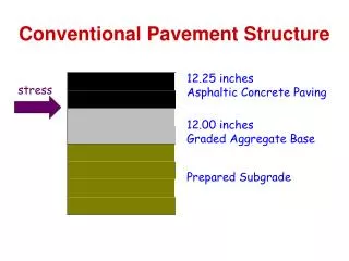
Pavement Structure • Surface • Base • Subbase • Compacted subgrade • Natural subgrade • Bases and subbases are usually granular material or agg. • Subbase – not as high of a material • Compacted subgrade – layer of the subgrade compacted in cut areas – or embankment material in fill zonez
Pavement • Main function is to reduce the high unit stresses imposed by vehicles on the surface to stresses on the subgrade that are low enough to carried with out failure due • Failure occurs • Rutting • Excessive settlement • Or other types of distress • Magnitude of stress reduction is mainly function of thickness of pavement
Major factors involved in design of pavement thickness • The magnitude of imposed loads • The strength of the sub grade soil • A typical city design • Arterial roads • 3in asphalt concrete • 6in granular base • 12 granular sub base • Local roads • 1 ½ in asphalt concrete • 6in granular base • 6 in granular sub base • Rural roads • 6 in granular base with an asphalt seal coat • 6 in granular sub base
Measurement of the design load for pavement • Difficult to determine because • Wheel loads – which vary • Load application vary from a few thousand to many millions per year • Growth in the amount and type of traffic • The decrease in serviceability due to age – climate and type of traffic must be taken into account • Various methods have been developed by highway authorities • Aadt – average annual daily traffic • Dtn – design traffic number • Ewl – equivalent wheel loads • Esal – the total number of equivalent 18 kip (18,000 il or 80kn single axle loads expected on the pavement for the design period • Esal method was developed by asshto in the late 1950 – upgrade in 1993
Strength of sub grade soil • Soil strength will vary greatly along road route • However design can be changed continuously along route due to cost and construction problems • Climatic factors also play a role in strength assessment • Sub grade strength varies greatly between winter and spring • Estimate soil strength calculation • Group index (gi) indication of the silt and clay content of soil • Gi=(f-35)[0.2 + .005 (wl – 40)] =.01(f-15)(ip-10) • F = the percent passing the .075mm sieve • Wl= the numerical liquid limit expressed as a whole number • Ip=the numerical plasticity index expressed as a whole number • Example page 166 5-1
California Bearing Ratio (CBR) • 0riginally developed by California division of highways • Most common strength test conducted on soils for evaluation of sub grade quality • Compacting a sample at its optimum moisture content • Applying a surcharge to the sample to represent the estimated thickness of pavement over the sub grades • Soaking the sample for four days • Forcing a 19.4 cm2 plunger into the sample to a depth of 2.5mm . The force required to obtain this penetration is expressed as a percent of the standard load for crushed road base material
CBR test • Force required to pentrate the smaple 2.5 mm with the piston was .85kn • Cbr value is .85/13.3 = 6.4% = 6.4 • Modulus of sub grade reaction (k) • Calculated from a field test utilizing a 75 cm diamter plate on the sub grade – small plates on this large plate – jack to lift a load provide by a loaded transport over the plates – deflection of the plate is measure – modulus ofsub grade reaction is the load in pounds per square inch per inch of deflection • Resistance value (r) – this test value resulting from a soil test in a Hveemstabilometer
CBR Test continued • Resilient modulus (Mr) – test samples are taken from soil sampling tubes or remolded in 71 mm diameter molds at densty and moisture values representative of field conditions – they are then test in a modified triaxialceel – axial load is applied for .1 sec and removed for .9s – repeated 100 times • The resilient modulus (Mr) is the imposed repeated axial stress divided by the resilient axial strain
Thickness Design • Design charts – 5-3 page 168 • Example 5-3 page 167 • 3 ½ in surface • 4in base • 8 in sub base
AASHTO revised method • In 1993 • Includes the following • Subgrade soil strength is measured by the resilient modulus • The variation of the modulus during the year is determined and used in calculating an effective resilient modulus • Coefficients for various types of surfaces, bases , and subbases are calculated from the results of tests for elastic modulus for these materials • The formula for the structural number was modified as follows • Sn=a1d1+a2d2m2+a3d3m3 • Where m2 and m3 are modifying factors varying in the value between .40 and 1.40 depending on the drainage characteristics of the pavement structure • Other factors allow the design to take into account reliability, serviceability and standard deviation
ASSHTO Guide • Reliability (r%) = many factors involved • Suggested levels vary from 85-99.9 freeway in urban area • 80-99.9 freeway in rural area • 50-80 for all local roads • Collectors are rated at 80-95 urban • 75-95 rural roads • Overall standard deviation (s) – factors accounts for chance variation in traffic prediction and normal variation in pavement performance • .25 rigid and .35 for flexible pavements • Estimated total 18 kip equivalent load applications (w) – based on ESAL for the design period – reduced to give the value for the design lane – see chart page 173 • Effective roadbed soil resilient modulus – subgrade soil support value • Values for (Mr) are listed for each month • The average damage factor gives the effective resilient modulus for pavement design • Example – page 175 • Design serviceability loss – serviceability is defined as the ability of the pavement to serve the traffic – rated as 0 for an impossible road to 5 for perfect road
Subgrade construction • Consists mainly of • Compaction of the top layer in cuts and the whole dept of material in fills • Identification and treatment of unsuitable material • Unsuitable or borderline material includes • Organic and other compressed le soils • Areas subject to freezing temperatures • Top soil is the layer of most existing soils • Due to its high organic content it is quite compressible • Usually removed in fill area • If it is located within a meter or so of the final subgrade surface • Treatment • Floating the pavement • Excavation and replacement of the organic material • Displacement of the organic deposit using a surcharge • Use of geotextiles to separate base material from the subgrade and to reinforce subgrade strength
Frost Damage • Low class roads damage occurs in susceptible soils • Capillary rise in soils • Water rises in capillary tubes above water table inversely with average size of the pores in the soil structure • As freezing occurs water in the larger pores freezes • However the capillary water in adjacent smaller pores does not freeze – due to the depression of the freezing temperature in these very small volumes of water • Super cooled water moves to the previously formed ice crystals and freezes on the crystal • Ice lens may grow 2 to 4 inches • As freezing front penetrates farther more ice lenses are formed • This causes heaving in the road surface – can be as large as 1’
Frost Damage • During thawing of heaved soil • Pavement breakup may occur • Frost boils or wet potholes are formed on the surface as the roadbed thaws • Due to excess water and loose condition of the roadbed • Frost damage occurs when • Freezing temperatures • Source of free water • Frost susceptible soil
Cycles of Freeze thaw • Damage can increase during cycles of freeze thaw • Source of free water is groundwater • Susceptible soils • Have fairly high capillary rise • Permeable enough to allow water to transport through layers • Silts , silty clays, very fine sands , sands and gravels with silt or clay fines
Techniques to control frost damage • Removal and replacement of frost susceptible material within all or part of the zone of frost penetration • Insulation of the susceptible soil with rigid foam sheets to reduce the depth of frost penetration • Deepening of ditches or provision of sub drains to lower the water table • Construction of capillary cutoff layers made up of coarse sands or waterproof sheets below the susceptible soil • Construction of a thicker stronger pavement structure over susceptible or questionable soils
Sub grades and rigid pavement • May require additional controls • Sub grade should provide uniform support • May be necessary to mix the type of soil found along the route • Concerns about sub grade for rigid pavements • Frost heaving • Expansive soils • Mud pumping
Expansive soils and Rigid Pavement • May cause swelling and shrinking of the sub grade • Resulting in distortions of the pavement surface • A-6 or a-7 –AASHTO or MH,CH,OH Unified system are know types of expansive soils • To avoid problems • Compaction must be done at 2% above the optimum value • Swelling is controlled – soil do not absorb much more water • Mud-pumping • Displacement of fine soil particles and water through cracks, joints and the edges of the pavement due to heavy axle loads • Can lead to uneven support under slab • To control the problem – a layer of very permeable granular sub base may be required • Should also have low plasticity • Not over 15% passing the no . 200 sieve
Granular base and sub base course • Base course • Composed solely of granular materials –aggregates • Or soil or granular materials stabilized by an additive • Flexible pavement • Must help to distribute the load • Strong enough to carry the load without shear failure and resultant rutting • Must allow water to drain • If water is not allow to drain – water fills the pores and reduces the frictional support of the particles • Must resist frost • Must also prevent infiltration of sub grade materials
Granular base and sub base courses • Sub bases for flexible pavement • Must drain easy – to prevent frost • Strength not as important as base layer • One granular course required for rigid pavement • Usually called sub base • Main function to prevent pavement pumping • Creation of a shallow void under the slab due either to slight slab deflection with each load or to curling of the slab caused by temperature variations between the top and bottom of the slab • Water filing the void space due to infiltration of rain or other causes • Mixing of water and fines in the underlying material • Ejection of this mixture at joints and edges of the pavement as each wheel load cause the slab to deflect
Granular Base and sub base courses • Rigid pavement -large voids have been created under slabs by pumping • Sub base to prevent pumping • Less than 45% passing no. 200 • Have a maximum plasticity index of 6 • Heavy loads change values to 15% no 200 and plasticity index and liquid limit of 6 and 25
Granular base and sub base course • Flexible pavement bases – dense graded – fall within limits result in a curve of roughly maximum density • Flexible pavement sub bases – grading requirements are more open • Percent of fines is restricted to a low maximum • Maximum values for plasticity – to control the amount of clay fines • Maximum loss in abrasion test – to ensure hard aggregates • Maximum loss in soundness test – to prevent degradation due to cycle of freezing and thawing • Petrographic requirement – to govern overall aggregate quality
Drainage Issues • More attention is being focus on drainage these days • Drainage issues • Granular bases with fines have pour drainage • Also over time degradation of base course occurs – reducing permeability • Some fines are required to provide a dense stable base during construction • Stable base course required during service as well
Drainage Problems • Water enters the base through • Cracks and joint in the surface layer • Infiltration from groundwater • Bases that become saturated lose a portion of their load carry capacity • Excess water in the sub base increase frost damage