Download
1 / 23
530 likes | 2.03k Views
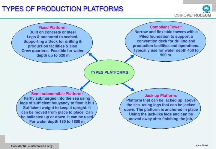
TYPES OF PRODUCTION PLATFORMS. Compliant Tower: Narrow and flexiable towers with a Piled foundation to support a convention deck for drilling and production facilities and operations. Typically use for water depth 450 to 900 m. Fixed Platform: Built on concrete or steel

E N D
TYPES OF PRODUCTION PLATFORMS Compliant Tower: Narrow and flexiable towers with a Piled foundation to support a convention deck for drilling and production facilities and operations. Typically use for water depth 450 to 900 m. Fixed Platform: Built on concrete or steel Legs & anchored to seabed. Supporting a Deck for drilling & production facilities & also Crew quarters. Feasible for water depth up to 520 m TYPES PLATFORMS Semi-submersible Platform: Partly submerged into the sea using legs of sufficient bouyancy to float it but Sufficient weight to keep it upright. It can be moved from place to place. Can be ballasted up or down. It can be used For water depth 180 to 1800 m Jack up Platform: Platform that can be jacked up above the sea using legs that can be jacked down. The platform is anchored in place Using the jack-like legs and can be moved away after finishing the job.
TYPES OF PRODUCTION PLATFORMS Floating Production System: FPSO, FSO, FSU. These are large ships that are equipped with production and some processing facilities Drillship: A maritime vessel that is fitted with drilling and production facilities for operations, especially deep water and remote operations. It is often fitted with a dynamic positioning system TYPES PLATFORMS Spar Platform: Tethered to the sea bottom by conventional mooring lines in stead of vertical tension legs. It could be conventional one piece cylindrical hull, the truss spar and the cell spar. Tension Leg Platform: These are floating rigs that are Tethered to the seabed to eliminate Most of the vertical movement using vertical tension. It can be used in water depth up to 2000 m.
TYPES OF OFFSHORE PRODUCTION PLATFORMS Source: Pat O’Connor, BP presentation, California & World Ocean’ 06, September 17-20
FUNCTION OF PRODUCTION FACILITY Function of Production Facility Water Separation Oil Separation Gas Separation Processing To Marketable Product Processing & Disposal Processing to Marketable Product
PRODUCTION MECHANISMS Production Mechanisms Secondary Recovery: Additional Recovery 15 to 20% Production Life 6-10 years Primary Recovery: Average Recovery < 30% In-situ Combustion Expansion of Dissolved Gas Existing Water Drive Water Injection Gas Injection Steam Injection Tertiary Recovery: (After secondary recovery) Average Recovery Additional 15 to 20% Produced by Pump MEOR LPG + Gas Drive CO2+ Water Surfactant Flooding Miscible Drive
PRODUCTION WELL http://upload.wikimedia.org/wikipedia/en/7/7f/Oil_Well.png
PRODUCTION MECHANISMS Primary Recovery Secondary Recovery http://www.maverickenergy.com/oilgas.htm
PRODUCTION MECHANISMS http://www.cogeneration.net/enhanced_oil_recovery.htm
SEPARATION PROCESS Light HC component flashing to the vapour phase depends on its partial pressure Partial Pressure of a component =( No. of molecules of a component / No. Molecules of total component in vapour phase) X Separator Pressure Higher the initial separator Pressure, greater the amount of Liquid in the separator Depends on separator Pressure Higher the separator Pressure, greater the partial pressure Too high initial Separation pressure, too many light component in separator liquid Greater the partial Pressure, higher the tendency to liquid phase Too low initial separator Pressure, few light Components in separator liquid Light HC components Will be lost to gas phase at the tank Light HC components is lost to the gas phase
SEPARATED OIL CHARACTERISTICS AND PROCESSING REQUIREMENT OIL PROCESSING Water Removal to 0.5 to 3% Salt Removal to 10-25 lbs/1000 bbls Basic Sediment Removal to 0.5 to 3% Direct Fired Heater Hydro- cyclones Filters Dilution With FW Water Removal Settling Tanker Truck Stock Tank Waste Water Skimmer Vessel Well Head Pipe Line Separator Heater
SEPARATED GAS CHARACTERISTICS AND PROCESSING REQUIREMENT GAS CHARACTERISTIC & PROCESSING Water Vapour Saturated Requires Dehydration to 7 lb/MMscf Gas Glycol Dehydration Pumping Dry Glycol Wet Glycol Separation Strips Gas From Water Vapour Dry Glycol Boiling In Reboiler Water Boiled off
PIPE CONSTRUCTION FOR OIL AND GAS TRANSPORTATION Pipe Line Construction: Transport O &G to storage Processing & Distribution Onshore Offshore Vegetation & Surface Anomalies Removal Assembling Pipe Section on a Lay Barge Prevent Pipe Line Movement Prevent Anchor Damage Pipe Stringing Individual Pipe Section May be 80 ft Jetting using a sled To dig a trench 3 ft Below Mudline For Pipe >8 in dia & Water Depth <200 ft Lowering String Into sea and placement Into the trench Trench Digging 5-6 ft deep. Must be Below 30 in any event Prevent Damage By Boat traffic Prevent Fishing Gear Damage
OIL AND GAS PRODUCTION AND PROCESSING FACILITIES Onshore Water Injection Onshore Separation Onshore Gas Lift Gas Terminal Onshore oil production Subsea Separation Subsea Tie-back Onshore Gas Compression Onshore Pipeline Offshore Gas Lift Gas Terminal Offshore oil production Offshore Gas Compression Offshore Pipeline Offshore Water Injection
TERRA NOVA FPSO http://upload.wikimedia.org/wikipedia/en/c/c7/Terra_Nova_FPSOmodule.jpg
TYPICAL OIL & GAS PRODUCTION FLOW DIAGRAM OF A FPSO http://upload.wikimedia.org/wikipedia/en/c/c7/Terra_Nova_FPSOmodule.jpg
FPSO FUNCTIONS Produced Oil/gas collection from Production platform Processing FPSO FUNCTIONS Offloading Storage Tanker Pipeline
CHARACTERISTIC FEATURES OF WORLD”S LARGEST FPSO Building Cost US$800.00 MM Storage capacity 2.2 MM bbls FPSO KIZOMBA A L = 285 m W= 63 m H = 32 m Built by Hyundai Heavy Industries Operated by Esso Exploration Angola Operating Water Depth: 1200 m Weight = 81,000 tones
ESP SYSTEM A special motor with a high voltage (3-5 kV) AC current source, Temp 150 oC, Pressure 5000 psi, depth 12000 ft, energy 1000 HP A staged series of Centrifugal pumps to Increase wellbore fluid pressure ESP System Not very tolerant to Solids such as sands Due to high rpm ( up to 4000) and tight clearance Low efficiency with Significant gas fraction, > 10% http://upload.wikimedia.org/wikipedia/en/7/7f/Oil_Well.png
PUMPJACK OR PUMPING UNIT • Pump jack/Pumping Unit: Overground drive for a reciprocating piston pump. It is used to mechanically lift liquid if there is not enough reservoir pressure. • The pump jack converts the rotary mechanism of the motor to a vertical reciprocating motion to drive the pump shaft vertically up and down. • The engine of the pumping jack runs a set of pulleys to transmit the power to drive a pair of cranks. The cranks have a counter weight on them to assist the motor to lift the heavy string of rod. • The cranks in turns raise and lower one end of an ‘I’ beam which is free to move on an “A” frame. • The other end of the ‘I’ beam has a curved metal box known as horse/donkey head. • A metal cable or fiber glass known as bridle is connected to the horse head and the polished pipe. The bridle follows the curve of the horse head as it lowers or raises to create a completely vertical stroke. • Depending on the size of the pump, it generally produces 5 to 40 litres oil-water mixture per stroke
BEAM PUMP ELEMENTS Clamp: Gripping the polished rod body and holding the sucker rod string suspended Sucker & Polished Rods Transmit movement from the surface drive to the deep well plunger BEAM PUMP ELEMENT Coupling Joins sucker rods together • Centraliser • Centralising the sucker rod to protect tubing and sucker rod coupling. • Cleaning sucker rod and tubing from asphaltene, pitch & paraffin deposits. • Protecting sucker rod and tubing from high wear
SURFACE DRIVE FOR SCREW PUMP The surface drive of screw pump is designed for operation as a part of the unit for pumping-out formation fluid from the wells. http://motovilikha.perm.ru/mash/neften/neftepromen/
DOWNHOLE SAFETY VALVE (DHSV) • Down hole Safety Valve: These are usually uni-directional flapper valves which open downwards under the action of pressure applied from the surface. During well shut off, wellbore fluid pressure closes the valve thus isolate the reservoir fluids from surface. • Positioning of Downhole Safety Valve • Positioning High (Low Depth) – higher the position of the DHSV, lower the amount of HC above it when the well is shut off. Hence, in the event of any accident, there is no possibility of large volume of fluid spill and thus little environmental damage due to the spill. Also there is a lower scope fire and lower severity of fire. Therefore, placing the valve higher reduces hazards associated with spills and fire. • Positioning Low (High Depth) -Deeper the position of the DHSV, higher the amount of HC above it when the well is shut off. Hence, in the event of any accident, there is high possibility of large volume of fluid spill and thus high environmental damage due to the spill. Also there is a higher scope of fire and lseverity of fire. Therefore, placing the valve lower increases hazards associated with spills and fire. • Deeper the position of the DHSV, larger the hydraulic control line below the surface that are used to open the DHSV. Hence, the weight of the hydraulic fluid alone may apply sufficient pressure to keep the valve open, even with the loss of surface pressure. • Optimum Depth: The DHSV should be positioned subsurface to prevent any potential damage to it from risk of cratering in the event of a catastropic loss of the top side facility. It shoud be placed beyond the cratering risk depth.