Download
1 / 9
90 likes | 222 Views
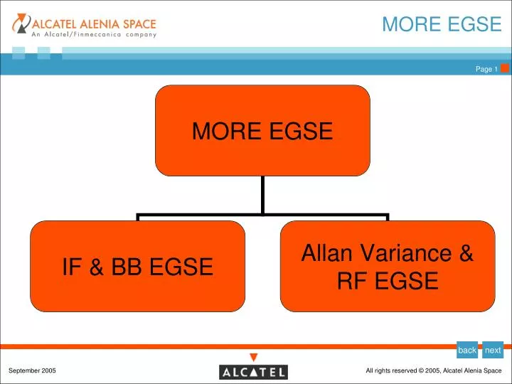
MORE EGSE. Phase A/B1- EGSE Activities-1. Beginning in January 2007: EGSE system definition including: Analysis of EGSE functional and performance requirements Analysis of the Radio-Science Experiment applicable documentation.

E N D
Phase A/B1- EGSE Activities-1 • Beginning in January 2007: • EGSE system definition including: • Analysis of EGSE functional and performance requirements • Analysis of the Radio-Science Experiment applicable documentation. • Definition of EGSE overall architecture and of the interfaces between main EGSE components (RF equipment, digital and power equipment, MMI workstations, etc.) • Establishment of an overall EGSE development plan and schedule • Produce the design specification • WBRS preliminary study including: • Analysis of the requirements related to the deep space ranging system with focus on the wideband ranging signaling system (WBRS). • Integrate the EGSE level simulation with system level simulations (developed by University of Rome).
Phase A/B1- EGSE Activities-2 • EGSE RF system definition including: • Analysis of EGSE RF functional and performance requirements • Definition of RF EGSE architecture • Contribute to overall EGSE development plan and schedule • Analyze the Radio-Science Experiment applicable documentation. • Analyze the requirements related to Allan Variance. • Produce the Allan Variance Test Set design specification • Implement the Allan Variance Test set to be used for B/B testing
BB Heritage SoftwarePlatform Operating System Red Hat Linux v.9.0 • Hardware Platform • Industrial PC equiped with: • IF receiver (up to 3) • IF Modulator (up to 2) • BPSK Dem. (up to 3) • Frame Synch +Vit. Dec. + RS Dec. (up to 3) • RNG Processor • TC Generator • IRIG-B receiver • Frequency Distributor • CPU • Hard Disk
Main Features: RANGING (1/2 cont.) • Ranging function • Code ranging ESA standard • interface the RF system by means the IF Receiver in down-link (the same as for the TLM link) and the IF Modulator for the Up-link link (the same as for the TLC link) • generate the ranging tone and the code for ranging measurements being the tone signal BPSK modulated by the ranging code; the tone frequency and code length are programmable whilst the Code Repetition Period may be computed by • the maximum usable code length is 2 Exp. 24 • supply the ranging signal to the IF Modem (the same of the TLC system) for PM modulation with the correct modulation index • receive from the IF receiver the down linked ranging signal for ranging measurements • solve code ambiguity due to the propagation delay • perform accurate range measurement by measuring the time elapsed between emitted and received code • store in mass memory the ranging measurements data • transmit to the SCC all the stored data by means of TCP/IP link according to the communication protocol
Main Features: RANGING (2/2) Summary of characteristics • Ranging tone 100 KHz to 1,5 MHz • Ranging modulation index 0,1 to 2 rad. (down-link) • Tone mod. two selectable phase (programmable from 10° to 90°) • Modulation scheme PCM/PSK/PM • Maximum code length 2 Exp 24 • Ranging accuracy 1ns • STC protocol MKII (modified) on TCPIP (IEEE 802.3) • M&C protocol EDEN protocol on TCPIP (IEEE 802.3)
WBRS migration • Main Improvements needed • WBRS standard • 20 MHz tone • Improved accuracy • Integration of post processing SW • Modification in architecture • Possible trough reconfiguration in FPGA • Possibility to change IF front end
FILTER + ZCD DUT TIME INTERVAL COUNTER L.O. REFERENCE OSCILLATOR FILTER + ZCD DUAL MIXER METHOD Allan Variance test set-up 1/2 • The test bench is designed in order to measure the Allan variance of frequency standards and it is known as Dual-Mixer Time Difference (DMTD) scheme • The L.O. frequency is set in order to have a residual frequency of 1 Hz, the time interval counter measures the time difference between the two signals, from the fluctuation of the time difference it is possible to calculate the Allan variance.
FILTER + ZCD TIME INTERVAL COUNTER L.O. REFERENCE OSCILLATOR FILTER + ZCD REFERENCE DUAL MIXER METHOD (NOISE FLOOR EVALUATION) Allan Variance test set-up 2/2 • The uncertainty sources are : • Reference oscillator residual phase noise. • Noise introduced from the ZCD ( Zero Crossing Detector ) • Measurement from “noise floor evaluation” test setup will allow to understand the real accurarcy of the test set up.