Download
1 / 19
190 likes | 410 Views
Mapping the GPS Multipath Environment Using the Signal-to-Noise Ratio (SNR). Andria Bilich*, Kristine M. Larson +. * Geosciences Research Division, National Geodetic Survey + Department of Aerospace Engineering Sciences, University of Colorado, Boulder. Overview. GPS background

E N D
Mapping the GPS Multipath Environment Using the Signal-to-Noise Ratio (SNR) Andria Bilich*, Kristine M. Larson+ * Geosciences Research Division, National Geodetic Survey + Department of Aerospace Engineering Sciences, University of Colorado, Boulder
Overview • GPS background • Motivation: multipath with GPS signals • Why do we care? • What do we know? • Measurement: SNR • Technique: power spectral mapping to image multipath environment National Geodetic Survey National Oceanic and Atmospheric Administration
Global Positioning System (GPS) • Radio navigation system • L-band • 1575.42 MHz (L1) • 1227.60 MHz (L2) • 24+ satellites • Global coverage • 4-10 in view at any instant courtesy of Dept. of Defense National Geodetic Survey National Oceanic and Atmospheric Administration
A rA B rB C rC Positioning with GPS • Trilateration using distance to satellites • Must have accurate satellite-receiver range National Geodetic Survey National Oceanic and Atmospheric Administration
Multipath with GPS • Range error = positioning error • Systematic (quasi-sinusoidal) • Site-specific National Geodetic Survey National Oceanic and Atmospheric Administration
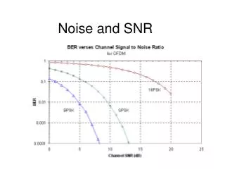
multipath composite direct Signal-to-Noise Ratio (SNR) • SNR • Recorded by GPS receiver • Strength of tracked (composite) signal • SNR = direct + multipath signals Multipath strength National Geodetic Survey National Oceanic and Atmospheric Administration
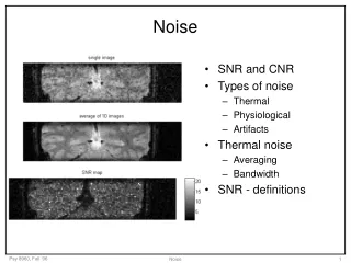
Multipath Oscillations in SNR • Phase relationship changes with satellite motion • Parameters affecting multipath frequency: • Reflector distance h • Reflection angle • GPS wavelength Multipath frequency National Geodetic Survey National Oceanic and Atmospheric Administration
Ground Distance vs. Multipath Period Fast MP = far away Slow MP = nearby For a fixed reflector, satellite motion generates time-varying signature National Geodetic Survey National Oceanic and Atmospheric Administration
Multipath and SNR:putting it all together • SNR: • Frequency = distance to reflector • Amplitude = multipath strength • Satellite position: • Azimuth/elevation = location of reflectors relative to antenna • Rate of motion = impact on frequency and height National Geodetic Survey National Oceanic and Atmospheric Administration
SNR Data • Total SNR = direct plus reflected signal(s) • Direct amplitude = dominant trend • Multipath signal = superimposed on direct National Geodetic Survey National Oceanic and Atmospheric Administration
Power Spectral Maps • Wavelet spectra of detrended SNR • Frequency bands of interest • Assign amplitude (power) to satellite position • Plot all points on a grid (sky map) National Geodetic Survey National Oceanic and Atmospheric Administration
Multipath from Nearby Structure: TRO1 • Antenna on a mast: • 4.09 m above ground surface • 1.3 m above flat tar-paper roof • Roof to S of antenna National Geodetic Survey National Oceanic and Atmospheric Administration
TRO1 Power Maps • High power at long periods = close-in reflector National Geodetic Survey National Oceanic and Atmospheric Administration
Multipath from Distant Topography: MKEA Mauna Kea (MKEA), Hawaii National Geodetic Survey National Oceanic and Atmospheric Administration
MKEA Power Maps 30-60s 10-30s 60-90s • Frequency (distance to reflector) changes with satellite position • High power returns from cinder cones National Geodetic Survey National Oceanic and Atmospheric Administration
Combined Multipath Environments: KYVW • Standard GPS monument ~ 1.8m above ground • Nearfield: sandy, flat ground • Farfield: gentle hillsides to NW and E National Geodetic Survey National Oceanic and Atmospheric Administration
KYVW Power Maps Ground reflections Long periods (L1) Short periods (L2) Reflections from hillsides National Geodetic Survey National Oceanic and Atmospheric Administration
Summary • SNR influenced by multipath • Image multipath environment using SNR frequency & amplitude + satellite position & motion • Determine which objects create multipath errors National Geodetic Survey National Oceanic and Atmospheric Administration
Acknowledgements • Tools: • Torrence and Compo wavelet toolbox: http://paos.colorado.edu/research/wavelets/ • Generic Mapping Tools (GMT) • IGS, CORS, SOPAC, UNAVCO, JPL • NSF grants and fellowships Bilich, A., K.M. Larson (2007) Mapping the GPS multipath environment using the signal-to-noise ratio (SNR), Radio Science, 42, RS6003. National Geodetic Survey National Oceanic and Atmospheric Administration