Download
1 / 43
430 likes | 893 Views
Principles of Orthogonal Frequency Division Multiplexing and Multiple Input Multiple Output Communications Systems. OFDM. OFDM Material. Multicarrier communications Synchronization Issues Synchronization Sidelobes OFDMA. Intersymbol Interference. BER Floor for various modulations.

E N D
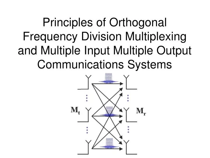
Principles of Orthogonal Frequency Division Multiplexing and Multiple Input Multiple Output Communications Systems
OFDM Material • Multicarrier communications • Synchronization • Issues • Synchronization • Sidelobes • OFDMA
Intersymbol Interference BER Floor for various modulations • Occurs when symbol period (Ts) is less than channel delay spread, • ISI introduces an error floor to BER • Limits maximum throughput • Solutions: • Equalization (high complexity) • Longer symbol periods (generally means lower data rate) QPSK limit J. C.-I. Chuang, "The Effects of Time Delay Spread on Portable Radio Communications Channels with Digital Modulation," IEEE JSAC, June 1987
Concept: Divide original data stream at rate R into L lower rate (R/L) streams on different carriers to increase symbol time Long history KINEPLEX ANDEFT KATHRYN Effects High receiver complexity separate receiver chain per carrier Bandwidth due to sidebands Each subcarrier experiences flat fading Bc Multicarrier communications: Longer period, same data rate J. Andrews, A. Ghosh, R. Muhamed, Fundamentals of WiMAX, Prentice Hall, 2007 B/L f B
Much simpler to create multicarrier transmission using iFFT Information carried in magnitude and phase of each bin Then can be recovered by using FFT at receiver Inverse Fourier transform would be an infinite duration sine wave Cut at Symbol duration Ts Rectangular windowing causes sinc spectrum in frequency domain with zeros at 1/Ts Orthogonal subcarriers OFDM
Guard intervals and intersymbol interference • If we space OFDM symbols by gaps at least as long as the delay spread, then there will be no intersymbol interference • However, there will still be interference within the symbol Guard interval Guard interval OFDM Symbol OFDM Symbol OFDM Symbol Delay Spread Delay Spread
Equalization and the DFT • While using longer symbol timing means OFDM can avoid irreducible errors, still have interfering energy in band from multipath • Received signal is the (linear) convolution of channel impulse response with transmitted signal • DFT Circular Convolution Theorem • Circular convolution of two discrete vectors in time domain • Is multiplication in the frequency domain • Implication: If we can make the system behave like a circular convolution, equalization is trivial • complex multiplication per FFT bin at the receiver
Cyclic Prefix • Adding a cyclic prefix at transmitter leads to circular convolution • Note that misaligned timing still results in a circular convolution, just time shifted • Makes for phase shifts in FFT bins • Correct that in a moment J. Andrews, A. Ghosh, R. Muhamed, Fundamentals of WiMAX, Prentice Hall, 2007
We’re transmitting redundant bits (no information transfer) Bandwidth penalty: L / (L + v) Power penalty: L / (L + v) Penalty becomes negligible as L becomes large (but there are tradeoffs! – more later) Power penalty generally more important in practice where systems are interference limited Penalty can be avoided with zero prefix Nothing transmitted in guard band (zero prefix) Receiver adds tail back to beginning of symbol Used in WiMedia Permits low complexity equalization for same data rates Single carrier tap# approximately bandwidth delay product MAC OFDM, number subcarriers grows with bandwidth-delay product, so Comments on Cyclic Prefix J. Andrews, A. Ghosh, R. Muhamed, Fundamentals of WiMAX, Prentice Hall, 2007
Frequency Errors • Primary sources of frequency errors • Doppler shift • Clock mismatches • Phase noise • Effects • Reduction in amplitude (missampling sinc) • Intercarrier interference O. Edfors, M. Sandell, J. van de Beek D. Landström, F. Sjöberg, “An Introduction to Orthogonal Frequency Division Multiplexing,” Sep 98, Available online: http://epubl.luth.se/avslutade/0347-0881/96-16/esb96rc.pdf
Effects of Frequency Errors Fading Channel AWGN • Comments • Impact greater for higher SNR signals • Note 5% estimation error can lead to 5 dB effective degradation at 64-QAM like SNRs • Big frequency impact is why OFDM was originally for fixed deployments • Techniques • Data aided • Non data aided • Cyclic prefix O. Edfors, M. Sandell, J. van de Beek D. Landström, F. Sjöberg, “An Introduction to Orthogonal Frequency Division Multiplexing,” Sep 98, Available online: http://epubl.luth.se/avslutade/0347-0881/96-16/esb96rc.pdf
Solution Techniques Spectral Effects of Windowing and Clipping • Clipping • Eliminate signals above a certain level or ratio • Peak windowing • Filter peaks • Linear block code • Select only those codewords with small PAPR • Can also provide error correction • Peak Cancellation • Subtract signals from high peaks • Need to be similar bandwidth to limit out-of-band interfernce • Symbol Scrambling Peak Cancellation, Clipping, PAPR = 4dB
Time Domain Frequency Synchronization • Complex baseband model of passband signal • ftx is transmitter carrier frequency, Ts is symbol period, sn is transmitted signal • Received
Time Domain Frequency Synchronization • Evaluate sum of products of time-delayed and conjugated repeated symbols
Estimator • Frequency offset estimator • Ambiguity limit • When D = Ts • In AWGN, this is the maximum likelihood detector with variance proportional to
Frequency domain (post-FFT) • Similar estimator evaluated on Fourier Transformed signal • So same performance, but much more complex as the DFT has to be calculated for both repeated symbols.
Channel Estimation • Channel assumed static for duration of symbol, though frequency/phase varying over bandwidth • Solution, embed pilot symbols at regular intervals in the symbol • Used closest pilot • Interpolate From IEEE Std 802.16-2004
More synchronization • Need to detect beginning of packet • Energy detect • Measure energy, see when it exceeds threshold • Packet detection • Correlate with known sequence • Delay and correlate • Symbol timing • No problem to be off by a fraction of the guard interval from perspective of DFT • Bad timing does get ISI though from cyclic prefixes • Better to be early (low ISI) than late
Synchronization all together • Steps: • Detect packet beginning • Align symbol boundary • Perform coarse frequency/timing synchronization • Perform fine frequency/timing synchronization • Track changes in channel as needed Identical symbols 802.11a Framing
Peak-to-Average Power Ratio • Sum of large number of (somewhat) independent subcarriers leads to signal distribution that is somewhat Gaussian • Implications • long tails for amplitude distribution • Possibly large ratios of peak-to-power ratios • Long tails can drive amplifiers into nonlinear region • Introduces harmonics and significant out-of-band spectral energy PAPR CDF for Varying # Subcarriers
Bc Adaptive Modulation B/L • Different subcarriers experience different flat fades • Means different SINR • Adapting modulation scheme of each subcarrier to its SINR allows the system to approach Shannon capacity B/L f B J. Andrews, A. Ghosh, R. Muhamed, Fundamentals of WiMAX, Prentice Hall, 2007
Multiple user access with OFDM Lots of flexibility possible when splitting up OFDM symbols and frames Assign different subcarriers to different users Assign different time slots to different users Vary modulation and coding Vary powers More options available with antenna arrays Allocation algorithms Maximum Sum Rate Proportional fairness Proportional rates constraints OFDMA J. Andrews, A. Ghosh, R. Muhamed, Fundamentals of WiMAX, Prentice Hall, 2007
The use of multiple antennas provide two forms of diversity: Diversity gain Exploit multiple independent channels created by multipath diversity Works with uncorrelated antennas Array gain Coherently combine energy from antennas Works even with perfectly correlated antennas as received SNR increases linearly with the number of receive antennas Adding additional transceiver chains is expensive (SWAP and cost), but can provide tremendous (though competing) gains Increase the system reliability (decrease the bit or packet error rate) Increase the achievable data rate and hence system capacity Increase the coverage area Decrease the required transmit power 10 5 Fading Envelopes [dB] 0 -5 -10 0 200 400 600 800 1000 Samples Antenna Array Principles
Receive Diversity Selection Diversity • Oldest and simplest diversity technique • Receiver leverages independence of fades on antennas • Selection Combining (SC) • Choose antenna with maximum SINR • Lowest complexity • Equal Gain Combining (EGC) • Phase align and sum signals across antennas • Maximum Ratio Combining (MRC) • Weight signals by SINR • Best performance (system SINR is sum of antenna SINRs) Average SNR Improvements MRC EGC SNR (dB) SC Antennas
Transmitter sends multiple signals (possibly copies) These interfere at the receiver, but if coded properly, the receiver can recover the signal Simplest implementation is orthogonal space time block codes or Alamouti codes1 Assumes flat constant channel over two symbol periods (may not be true for high mobility) Requires channel knowledge at receiver No change in rate required Receiver Alamouti Operation Output SNR 2x1 Alamouti Open Loop Transmit Diversity (1/2) h1 RX Decoder TX Encoder h2 1. S. M. Alamouti, “A simple transmit diversity technique for wireless communications,” IEEE Journal on Selected Areas in Communications, vol 16 pp.1451–1458, Oct 1998
Open Loop Transmit Diversity (2/2) A 4x2 Stacked Alamouti System • 2x2 STBC (same transmit encoder) SINR • Note number of h terms maximized when Nt = Nr for a fixed number of antennas • Also full-diversity, orthogonal STBCs exist only for certain combinations of Nt and Nr. • Can also use space-time trellis codes for added 1-2 dB, but those have exponential complexity order J. Andrews, A. Ghosh, R. Muhamed, Fundamentals of WiMAX, Prentice Hall, 2007 Comparison of STBC and MRC
Space-Time Trellis Coding • Convolutional code applied to space and time domain • Each antenna output is mapped into modulation symbol • Maximum likelihood sequence estimator ( Viterbi algorithm) Example) Delay Diversity (by Wittneben [4]) Generator matrix form Encoder structure for two antennas [a1 a2 a3 a4] QPSK mapping
Transmit selection diversity Antenna(s) chosen which maximizes SINR Equivalent to receiver selection diversity Not as good as beamforming Little bandwidth required Makes most sense in in deployments with small bandwidths and small delay spreads (low range) Linear diversity precoding Feedback channel state information to transmit encoder Transmit encoder then attempts to fine encoding matrix which maximizes SNR at the receiver Higher SNR than STBC Typically use some sort of codebook to reduce feedback bandwidth Closed Loop Systems
interferer desired signal Beamforming Systems Narrowband adaptive array or linear combiner • The weight vector is adjusted to improve the reception of some desired signal • Angle of arrival • MUSIC, ESPRIT • Eigenbeamforming • No physical interpretation, but useful in multipath environment • Minimize some cost function • Useful for interference rejection, multipath fading mitigation, and increased antenna gain
Adaptive Beamforming • Narrowband beamforming is equivalent to spatial filtering • By choosing appropriate sensor coefficients, it is possible to steer the beam in the desired direction • By varying the sensor coefficients (spatial filter taps) adaptively, the interference is reduced • Wideband beamforming requires joint space-time processing • Phase shift at the antennas is frequency dependent • Frequency-dependent response is required (filter) • Common algorithms • Maximum Signal to Interference and Noise Ratio (MSINR) • Minimum Mean Squared Error • Least Mean Squares • Minimum Variance Distortionless Response (MVDR) • Recursive Least Squares • Similar to linear precoding, but may account for interferers
Performance Comparison • MRT refers to maximum ratio transmission • the choice of antenna weights that maximize received SNR • With optimal eigenbeamformer, canceling an interferer is equivalent to dropping and antenna element 3 dB Modified from: J. Andrews, A. Ghosh, R. Muhamed, Fundamentals of WiMAX, Prentice Hall, 2007
Spatial Multiplexing • In rich scattering environments, independent data signals transmitted from different antennas can be uniquely decoded to yield an increase in channel capacity
Open loop (Unknown channel) Maximum likelihood Little gain, except at low SNR Zero-forcing Evaluates pseudo-inverse of H Can dramatically increase noise power MMSE Minimizes distortion Like Zero-forcing at high SNR, but without the instability at low SNR BLAST Layers & codes transmissions across antennas Effectively linear receiver with successive interference cancellation Receiver iterates through transmission streams using MMSE or ZF Works better in lab than real-world due to high SNR requirement Closed loop (known channel) Singular Value Decomposition Computationally complex Capacity (assuming waterfilling) For large SNR, capacity grows linearly with rank of H, approximately min{Nt, Nr} Approximations guided by information capacity, error probability detection MSE received SNR Can tradeoff multiplexing for diversity Spatial Multiplexing Techniques
19 BS, 3 sectors, spaced 2.8 km, mix of users Proportional Fair scheduling Relative Capacity as function of Antenna Array Technique Source: WiMAX Forum
Concept: Leverage other radios to effect an antenna array Applications: Extended vehicular coverage Backbone comm. for mesh networks Range extension with cheaper devices Issues: Timing, mobility Coordination Overhead Cooperative Antenna Arrays Cooperative MIMO Second Hop First Hop First Hop First Hop First Hop First Hop First Hop Relay cluster Relay cluster Relay cluster Relay cluster Relay cluster Relay cluster Destination Cluster Source Cluster Source Cluster Source Cluster Source Cluster Source Cluster Source Cluster Transmit Diversity destination source
Spacing between antennas influence correlation and coupling Multipath components can act like interference for beamforming which reduces antenna gain Correlation/Coupling Effects Beamforming BER 4x4, SNR = 20 dB, 30 AS http://www.ngwnet.ac.uk/files/wspres/mimo2.thompson.pdf [Ref. D. Figueiredo, WPMC’04]
Diversity Combining Combine signals from different antenna elements using various algorithms Signal from each element is processed separately Signals have to be uncorrelated for maximum performance Mitigates fading Increases gain Can improve polarization match No interference rejection capabilities Adaptive beamforming Focus the antenna’s gain in the direction of the desired signal Achieved by manipulating the weights associated with each element Antenna elements have to be separated by /2 to attain a certain phase difference in the signals Signals are correlated All advantages of diversity combining Has interference rejection capabilities Typically > 20 dB Diversity vs. Beamforming
OFDM Summary • OFDM overcomes even severe intersymbol interference through the use of the IFFT and a cyclic prefix. • Limiting factor is frequency offset • Correctable via simple algorithm when preambles used • Two key details of OFDM implementation are synchronization and management of the peak-to-average ratio. • OFDMA provides a lot of flexibility to a system’s resource allocation • Permits exploitation of multi-user diversity
MIMO Summary • Spatial diversity offers incredible improvements in reliability, comparable to increasing the transmit power by a factor of 10–100. • These diversity gains can be attained with multiple receive antennas, multiple transmit antennas, or a combination of both. • Beamforming techniques are an alternative to directly increase the desired signal energy while suppressing, or nulling, interfering signals. • In contrast to diversity and beamforming, spatial multiplexing allows multiple data streams to be simultaneously transmitted using sophisticated signal processing. • Since multiple-antenna techniques require channel knowledge, the MIMO-OFDM channel can be estimated, and this channel knowledge can be relayed to the transmitter for even larger gains. • It is possible to switch between diversity and multiplexing modes to find a desirable reliability-throughput operating point; multiuser MIMO strategies can be harnessed to transmit to multiple users simultaneously over parallel spatial channels. J. Andrews, A. Ghosh, R. Muhamed, Fundamentals of WiMAX, Prentice Hall, 2007
Useful References • O. Edfors, M. Sandell, J. van de Beek, D. Landström, F. Sjöberg, “An introduction to orthogonal frequency division multiplexing,” Sep 1996. • A. Bahai, B. Saltzbeg, M. Ergen, Multi-Carrier Digital Communications Theory and Applications of OFDM, Springer 2nd edition, 2004. • J. Andrews, A. Ghosh, R. Muhamed, Fundamentals of WiMAX, Prentice Hall, 2007