Download
1 / 16
160 likes | 282 Views
Compton based Polarized Positrons Source for ILC. V. Yakimenko 1 , D. Cline 2 , Ya. Fukui 2 , V. Litvinenko 1 , I. Pogorelsky 1 , S. Roychowdhury 3 1 BNL, 2 UCLA, 3 Duke Univ. POSIPOL 2006 Workshop CERN 26-27-28 April 2006. ILC Source requirements.

E N D
Compton based Polarized Positrons Source for ILC V. Yakimenko1, D. Cline2, Ya. Fukui2, V. Litvinenko1, I. Pogorelsky1, S. Roychowdhury3 1BNL, 2UCLA, 3Duke Univ. POSIPOL 2006Workshop CERN 26-27-28 April 2006
ILC Source requirements * The length of the bunch train in ILC is 2820x300ns = 0.85 ms or 250 km. Bunch spacing has to be reduced in the dumping ring. ** Polarization level defines conversion/capture efficiency of polarized g rays into polarized positrons. 60% level corresponds to ~1.5% efficiency.
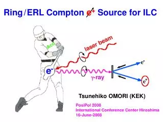
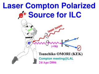
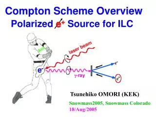
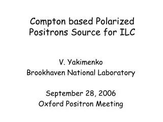
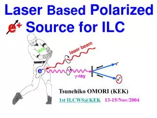
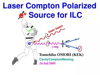
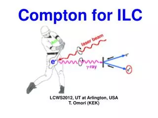
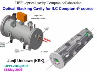
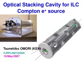
Polarized Positron Production: Compton Ring Scheme: CO2 Version (Omori, et al.)
g to e+ conv. target 4GeV 1A e- beam 30MeV g beam 15MeV e+ beam ~2 m Polarized Positrons Source (PPS for ILC) Conventional Non-Polarized Positrons: In our proposal • polarized g-ray beam is generated in the Compton back scattering inside optical cavity of CO2 laser beam and 4 GeV e-beam produced by linac. • The required intensities of polarized positrons are obtained due to 10 times increase of the e-beam charge (compared to non polarized case) and 5 to 10 CO2 laser system IPs. • Laser system relies on the commercially available lasers but need R&D for the new mode of operation • 5ps 10J@0.05 Hz CO2 laser is operated at ATF
Choice of parameters Ng ,Ne and Nfare the numbers of g-rays, electrons and laser photons, S is the area of the interacting beams and sC is the Compton cross sections • ~40 mm laser focus is set by practical considerations of electron and laser beams focusing and requires ~5 ps long laser pulses • Nonlinear effects in Compton back scattering limit laser energy at ~1J • Pulse train structure of 2820 bunches is set by main linac. • ~300ns bunch spacing in the main linac will be changed in the dumping ring in any design. 12 ns bunch spacing is selected to optimize linac acceleration gradient. • Train of ~10 nC electron bunches is required to produce 1012 polarized gammas per bunch. (~1 g-ray per 1 electron per laser IP) • Reduction of charge in the bunches (stacking of the positrons) leads to increase in the average power of the laser and electron beams • Conversion efficiency of polarized gammas into captured polarized positrons is assumed at ~1.5% and is subject of optimization. • The size of the gamma beam on the conversion target is expected to be much smaller when compared to other schemes due to the compact design of the Compton backscattering region. • Laser and drive linac are operated at 150Hz to optimize its performance. Train of 100 bunches is generated with 150Hz. 30 pulses are needed to form ~3000 bunches of ILC beam, stored in the dumping ring.
Ring or Linac? Stacking or No-stacking? • RMS energy spread in 6 GeV Compton ring ~2% for CO2 laser interaction with 4MW in synchrotron radiation. Difficult ring and very difficult laser (high repetition rate, average power, cavity stacking). • Head on Compton back scattering will be realized in the Linac design (electron beam will pass through small halls in the mirrors.) • Aperture requirements for the ring design dictate less efficient small angle Compton back scattering scheme. • For scheme without accumulation the main issue is high current ~4A in macro pulse (requires short accelerator sections, more klystrons and longer linac or a ring to change bunch spacing from ~12ns to 3ns). • The average beam power is increased with higher repetition rate required for the scheme with accumulation. It is 3MW for 150Hz. SC and NC linac structures can be used. Very difficult laser • Simpler damping ring and laser system at 5Hz for the scheme without accumulation might offset linac complexity.
Kerr generator 8 x 200ps CO2 oscillator Laser system for PPS 1x150ns Ge optical switch 8 x 5ps 1mJ 8 pulses, 5ps, 10mJ (YAG laser) Regenerative amplifier PC TFP TFP 8x5ps 10mJ PC amplifier 8x300mJ BS 8x30mJ 8x 30mJ 5ps • Train of 8 pulses spaced by 3 ns and 5 ps long sliced with a YAG beam from a 150 ns CO2 oscillator pulse • This train is seeded inside a regenerative amplifier cavity that has a round-trip time (3ns x 8=24 ns) • Amplified 8 pulses are dumped from the regenerative cavity with a Pockels cell and, after amplification, split with partial reflectors in 10 beams. • After amplification to 1 J/pulse, each 8-pulse train is injected into a ring cavity individual for each IP • An intracavity amplifier serves just to compensate optical losses during 8.5 s time interval needed for interactions with 2820 electron bunches. amplifier amplifier 8 x 1J 5ps 8 x 1J 24ns ring cavities (8 pulses x 3ns spacing) 1J / pulse sustained for 8.5 ms amplifier amplifier IP#1 IP#10
Laser system for PPS • Optical slicing and amplification of 5 ps CO2 pulses has been demonstrated and utilized in routine ATF operation for user experiments. • CO2 oscillator and initial amplifiers are commercially available lasers from SDI and operate at rep. rate up to 500Hz. • Final intracavity amplifiers shall operate at average power ~0.75 kW in non standard mode of operation. • Another issue to be addressed by industry is fabrication of optical elements to withstand high intracavity laser power.
Lasers from SDI http://www.lightmachinery.com/SDI-CO2-lasers.html WH20 WH100 WH350 WH500 Wavelength 9 – 11µm, Line Tunable Continuous 20 Hz 100 Hz 350 Hz 500 Hz Repetition Rate Pulse Energy 1.5 J Mode Type Multimode Optional: TEMoo, custom beam shapes, SLM Beam Size 13 x 13 mm2 Average Power 30 W 150 W 525 W 750 W Power Stability < 7 %
Compton Experiment at Brookhaven ATF(record number of X-rays with 10 mm laser) • More then 108 of x-rays were generated in the experiment PR ST 2000. NX/Ne-~0.1. • (0.35 as of April 2006- limited by laser/electron beams diagnostics) • Interaction point with high power laser focus of ~30mm was tested. • Nonlinear limit (more then one laser photon scattered from electron) was verified. PRL 2005. Real CCD images Nonlinear and linear x-rays
Compton Experiment at KEK ATF(polarized positrons with 532 nm laser) • Experiment demonstrated beam of 106 polarized -rays (PRL 91/16, 2003) • Experiment demonstrated 104 positron beam with 79% polarization level (KEK Preprint 2005-56, PRL 2005)
Laser R&D • 1st year: (2 Post Doc + $250K equipment) • Demonstrate slicing of a train of eight 5-ps CO2 pulses (based on existing ATF laser systems) • Simulations of the ILC laser system. • Design and purchase of custom CO2 amplifier ~5J/pulse, 150 Hz • Design of photocathode/slicing laser • 2nd year: (2 Post Doc + $700K equipment + room) • Dedicated YAG oscillator and amplifiers • Purchase of standard CO2 oscillator and amplifier @150 Hz • 8-pulse train amplification to 1J/pulse. • Delivery of custom CO2 amplifier ~5J/pulse, 150 Hz, 10 atm • 3rd year (2 Post Doc + $500K equipment) • Injection of 2-pulse train into interaction cavity and maintaining 100 intra cavity passes (total 200 pulses @ 1J/pulse, 150 Hz). • Intracavity laser/e-beam (60 MeV) interaction with production of trains of 100 6.5 keV x-ray pulses @ 6 Hz between trains with efficiency Ng/Ne-~1. • At the end of 3 year program we will have full scale prototype with one (out of five) interaction cavity @150Hz. The laser injection part will be fully functional.
The accelerator part of PPS proposal is based on the existing technologies and design can be completed in about 1 year. • 2nd and 3rd years of R&D will be focused on risk reduction
Cost speculationto prioritize R&D areas • @5Hz, 3 ns (no storage , 2820 per pulse) • CO2 Laser system @5Hz ~10M$ • 4Gev, 4A 5 Hz linac 10MV/m ~300M$ • Damping ring (2.5 km) ~200M$ • @5Hz, 6ns (no storage, 2820 per pulse) • CO2 Laser system @5Hz ~15M$ • 4Gev, 2A 5 Hz linac 15MV/m ~150M$ • Damping ring (5 km) ~300M$ • @150Hz (beam storage: 30 pulses 100 bunches each) • CO2 Laser system @150Hz 5-10M • 4GeV, 0.8A 150Hz linac 20MV/m ~100M$ • Damping ring (2.5 km) ~200M$ • Optimization is needed !
Conclusion • We propose Polarized Positron Source based on Compton back scattering inside optical cavity of CO2 laser beam and 4 GeV e-beam produced by linac. • The proposal requires high power picosecond CO2 laser mode of operation tested at ATF to generate 1 gamma per 1 electron per 1 laser IP. • The proposal utilizes commercially available units for laser and accelerator systems. • 3 year laser R&D is needed to verify laser operation in the non standard regime. • CLIC beam needs are easily satisfied due to lower beam intensity requirement and same rep. rate.