Download
1 / 34
340 likes | 586 Views
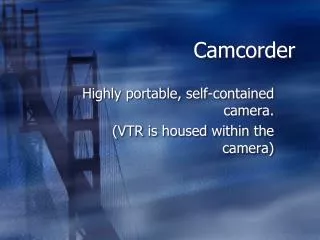
SPIRIT-C Solar Powered Image Response Infrared Tracking Camcorder. Justin Eiler Jeff Morroni Adeel Baig Andy Crahan Jim Patterson. SPIRIT-C Applications. Live Action Filming Security Surveillance Infant Monitoring Proximity Detection. Overview.

E N D
SPIRIT-CSolar Powered Image Response Infrared Tracking Camcorder Justin Eiler Jeff Morroni Adeel Baig Andy Crahan Jim Patterson
SPIRIT-C Applications • Live Action Filming • Security Surveillance • Infant Monitoring • Proximity Detection
Overview Pan/tilt tracking system for digital camcorder • Two stepper motors used for pan/tilt motion • Controlled by array of PIR(pyro-electric infrared) sensors • Solar array for supplying power to all components • External battery and camcorder battery charged through array • FPGA with embedded soft core for integration and control • Manual, and possibly wireless, controller
Block Diagram Solar Array Converters LED Cluster Battery Spartan 3 with Microblaze Manual Control H-Bridge Controller Stepper Motors Camera ADC / Mux Control Power Data IR Sensors
Camera Mount Assembly • The camera will be mounted into a cradle using existing tripod mount • The cradle is suspended between side holes on yoke • The yoke will be used to facilitate tilting motion • A Lazy Susan will be used for pan rotation and is connected to bottom hole of yoke
Stepper Motors • Two low power stepper motors will be used to power the rotation of the camera • The motors will also be Bipolar (no center taps)
Motor Control • A simple H-bridge circuit will be constructed to control the motors • The H-bridge will allow us the following modes
Motor Driver • The Step input will be hooked up to the Spartan 3 Pulse Width Modulator • The Direction input will be held high for clockwise or held low for counter clockwise • The outputs then will be attached to the appropriate H bridge inputs Y Step Winding 1 X Y Winding 2 Direction X Driver using TTL logic
IR Sensors • To detect rapid human movement will require high quality IR sensors • Several types are available including: - Thermopiles - Bolometers - Pneumatic Detectors - Pyroelectric Detectors
Pyroelectric IR Sensors • Only pyroelectric sensors have the rapid motion detection we require for high speed filming • These operate like current sources with output proportional to the rate of change in temperature • Extremely fast responses set them apart • They are also insensitive to undesirable external DC effects
Configuration • Internal FET detects surface charge changes • BW limited 2 stage amplifier reduces HF noise
Fresnel Lens • Fresnel lenses are • lightweight • economical • heat dissipative • precise • FL65 Detects 8-14um radiation
Fresnel Specs • Concentrates PIR field to 10 degrees versus 95 • Important aspect for sensitive motion detection • Provides appropriate field with our 8 sensor cradle design
Motion Detection • Motion detected by sensors being triggered consecutively • This cancels signals due to vibration, temp. changes, and sunlight
PIR325 Specs • 2 sensing elements • 5-14um response • General motion detector schematic
Solar Module • Maximum Power = 40 W • 25.8 inches by 21.1 inches • Provides 17.3Vmax and 2.31Amax • Manual/Automatic tilt for maximum sun intensity
DC/DC Converter Buck Converter • Input Voltage, Vg, will be around 17.3 V (for one panel) • Battery charging voltage should be around 13-14 V • Buck Converter will decrease the voltage with low loss
Control Technique • Output Voltage will be set to constant charging voltage • Sense the output current • FPGA will increase duty cycle thus changing the operating point • If new operating point has greater output power, continue increasing duty cycle, otherwise decrease
Deep Cycle Battery • 12V Deep cycle required for extended usage • A shunt regulator will prevent over-charging • When battery draws less current (fully charged), the regulator will dissipate the excess current
Starter Kit Features • Spartan-3 XC3S200FPGA • 2Mbit Xilinx XCF02S Platform Flash Prom • 1M-byte of Fast Asynchronous SRAM • 3-bit, 8-color VGA display port • 9-pin RS-232 Serial Port • PS/2-style mouse/keyboard port • Four-character, seven segment LED display • Eight slide switches • Eight individual LED outputs • Four momentary-contact push buttons • 50 MHz crystal oscillator clock source • JTAG port • AC power adapter with unregulated +5V power supply • On board 3.3V, 2.5 V, and 1.2V regulators
FPGA – Spartan-3 XC3S200 • 220K system gates, 4320 equiv. logic cells • 480 total CLB (configurable logic block) • 30K distributed RAM bits • 216K block RAM bits • 12 dedicated multipliers • 4 DCM (digital clock multiplier) • 173 user I/O, 76 differential I/O pairs CONFIGURABLE LOGIC BLOCK • Main logic resource for implementing synchronous and combinatorial circuits • Comprised of four slices • Two logic function generators, two storage elements, wide-function multiplexers, carry logic, and arithmetic gates • left-hand pair also supports: storing data using Distributed RAM and shifting data with 16-bit registers.
FPGA implementation • ISE development system: synthesis, mapping, placement, routing • I/O blocks and selectable paths create versatility • CLB’s are workhorse of FPGA Function Generator: LUT function used to implement state machine Storage Element: Flip Flop used to synchronize data to clock signal Carry chain: helps with fast arithmetic • PWM (pulse width modulator): clock divider binary up-down counter comparator
MICROBLAZE Embedded Soft Core - Based on RISC 32-bit architecture - 32-bit instruction word with three operands and two addressing modes - 32-bit address bus, 32 32-bit general purpose registers, single issue pipeline
User Interface • Switch between automatic and manual control • Allows user to control the camera position • Sega Genesis controller provides serial input (RS232 on DB-9) to the board
Camcorder Control • Camcorder remote will be incorporated into the Genesis controller
Constraints • Financial • LED cluster • Number of solar panels • Number of PIR sensors • Time • Real time data acquisition link • Wireless control • Digital peak power tracker • Automatic positioning for solar array
Contingency Plan • IR sensors • Switch to thermopile sensors • Use transmitter on subject • Camera • Use existing battery charger • Motor Control • Buy H-bridge controller if design performance bad
Division of Labor • Jeff – Solar array and peak power tracker • Adeel – Manual and Wireless control for the camcorder system • Jim – FPGA implementation and integration • Justin – Stepper motors, drivers, and H-bridge controller • Andy – Infrared sensor network and interface