Download
1 / 36
360 likes | 542 Views
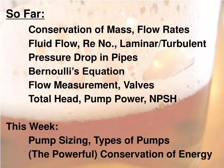
So Far: Conservation of Mass, Flow Rates Fluid Flow, Re No., Laminar/Turbulent Pressure Drop in Pipes Bernoulli’s Equation Flow Measurement, Valves Total Head, Pump Power, NPSH This Week: Pump Sizing, Types of Pumps (The Powerful) Conservation of Energy. Pump Sizing

E N D
So Far: Conservation of Mass, Flow Rates Fluid Flow, Re No., Laminar/Turbulent Pressure Drop in Pipes Bernoulli’s Equation Flow Measurement, Valves Total Head, Pump Power, NPSH This Week: Pump Sizing, Types of Pumps (The Powerful) Conservation of Energy
Pump Sizing • Volume Flow Rate (m3/hr or gpm) • Total Head, h (m or ft) • 2a. P (bar, kPa, psi) • Power Output (kW or hp) • NPSH Required
Pumps Centrifugal Impeller spinning inside fluid Kinetic energy to pressure Flow controlled by Pdelivery Positive Displacement Flow independent of Pdelivery Many configurations
Centrifugal Pumps Delivery Impeller Volute Casting Suction
Centrifugal Pumps Flow accelerated (forced by impeller) Then, flow decelerated (pressure increases) Low pressure at center “draws” in fluid Pump should be full of liquid at all times Flow controlled by delivery side valve May operate against closed valve Seal between rotating shaft and casing
Centrifugal Pumps Advantages Simple construction, many materials No valves, can be cleaned in place Relatively inexpensive, low maintenance Steady delivery, versatile Operates at high speed (electric motor) Wide operating range (flow and head) Disadvantages Multiple stages needed for high pressures Poor efficiency for high viscosity fluids Must prime pump
Centrifugal Pumps H-Q Chart Increasing Impeller Diameter Head (or P) A B C Volume Flow Rate
Centrifugal Pumps H-Q Chart Increasing Efficiency Head (or P) Required NPSH A B C Volume Flow Rate
Centrifugal Pumps H-Q Chart Head (or P) A B C Volume Flow Rate
Centrifugal Pumps H-Q Chart Required Flow Capacity Head (or P) Actual Flow Capacity Required Power Volume Flow Rate
Centrifugal Pumps Pump sizing example. Let’s say we need a pump for the following application: Total head: 40 m Flow rate: 2.5 m3/hr NPSH available: 2 m Using the pump curve provided last week. Select the appropriate impeller and determine the flow capacity with that impeller, pump power input, NPSH required and efficiency.
Centrifugal Pumps What if available NPSH is less than required NPSH? Increase Available NPSH 1. Increase suction static head (pump location) 2. Increase suction side pressure 3. Decrease fluid vapor pressure 4. Reduce friction losses on suction side Decrease Required NPSH 1. Reduce pump speed 2. Select a different pump
Centrifugal Pumps Curves created for specific speed, viscosity and density Often, use more charts or correction factors to “fine tune” pump selection Variable speed motor has same effect as impeller size Multiple pump/impeller combinations may work
Centrifugal Pumps Closed Impeller Most common, low solids Water, beer, wort Flash pasteurization Refrigerants Open Impeller Lower pressures Solids okay Mash to lauter turn Liquid yeast, wort, hops
Positive Displacement Pumps Theory: Volume dispensed independent of delivery head Practice: As delivery head increases, some slippage or leakage occurs Speed used to control flow rate, use of valves could cause serious damage Self-priming Good for high viscosities, avoiding cavitation
Positive Displacement Pumps Piston Pump Volumetric Efficiency High Pressures Metering hop compounds, detergents, sterilents Suction Valve Delivery Valve
Positive Displacement Pumps Peristaltic Pump
Positive Displacement Pumps Gear Pump High Pressures No Pulsation High Viscosity Fluids No Solids Difficult to Clean
Positive Displacement Pumps Lobe Rotor Pump Both lobes driven Can be sterilized Transfer Yeast Trub Bulk Sugar Syrup
Liquid-Solid Separation Types of Filtration Gravity, Vacuum, Pressure, Centrifugal Driving Force Dialysis Mechanical Electrostatic Magnetic Filtration Sedimentation
Filtration Media Glass fiber Paper fabric Monofilament cloth Metal or plastic mesh or screen Pack beds Bridging effect of filter cloth Filter cake buildup becomes “filter media”
Filtration • Performance of Filters • Ability to retain solids (high surface area) • Low flow resistance • Mechanical strength • Low cost • Inert to cleaning/processing chemicals • Brewery applications of filtration • Mash or Lauter tun – gravity filtration • Filtering wort and beer – pressure filtration • Separating beer from yeast – pressure filter
Liquid-Solid Separation Sedimentation – gravity or centrifugal Terminal settling velocity – time required TSV increases with: Larger particles Greater density difference between fluid, particle Lower fluid viscosity Next Slide: Shift Gears to Properties, First Law Drag Force Weight
Steam Table Examples Determine the phase, enthalpy and specific volume of the following: P = 1 bar, T = 25C P = 1 bar, T = 160C T = 150C, v = 0.5 m3/kg
Example • Determine the amount of energy required to heat 500 gallons of water from 20C to 220C at constant pressure (1.0 bar). • Enthalpy of fusion: 333.55 kJ/kg • Enthalpy of vaporization: 2260 kJ/kg • Specific heat of ice: 2.1 kJ/kg.K • Specific heat of liquid water: 4.2 kJ/kg.K • Specific heat of steam (cp): 2.2 kJ/kg.K) • 1 m3 = 264.2 gal
Laws of Thermodynamics • First Law – Energy is conserved • Second Law – Energy has quality, processes go in certain directions only • Forms of Energy • Potential energy = mgh • Kinetic energy = (0.5)mv2 • Internal energy (U) – microscopic forms • Conservation of Energy
Energy Interactions • Heat transfer – Temperature difference • Work – Shaft, electrical, boundary, etc. • Mass flow – U + PV = Enthalpy (H) • Closed System Energy Equation No PhaseChange
Open System Energy Equation for steady flow systems or
Example • A 2 m3 tank is filled to a pressure of 150 psig using an air compressor. After the tank has been filled, it’s temperature is 157F. Over the course of 20 hours, the tank cools to 56F. (cv = 0.718, cp = 1.04 kJ/kg.K). • a) Determine the mass of air in the tank. • b) Determine the pressure in the tank after it has cooled. • c) Determine the amount and average rate of heat transfer during the cooling process in kJ and W, respectively.
A 500 gallon water tank is filled with 220 gallons of hot water at 80C and 280 gallons of cold water at 10C. Assume that the specific heat of water is 4.2 kJ/kg.K. • Determine the temperature in the tank after it has been filled. • How much heat must be added to the tank to bring its temperature to 65C? • If a 30 kW electric heater is used, how long will the heating process take?
500 kg of grain (25C) is mixed with hot (80C) and cold (10C) water for mashing. The water to grain ratio (by weight) is 3:1 and the specific heat capacities of the water and grain are 4.2 and 1.7 kJ/kg.K, respectively. a) If the desired “mash in” temperature is 38C, how much hot and cold water should be added?
(Continued) A three step mashing process, with 20 minute-long rests at 50, 62 and 72C, is desired. The mash should be heated quickly, but not too quickly between rests; with an optimal rate of 1C per minute. Neglect heat losses to the surroundings. b) Plot the mash temperature vs. time. c) Determine the heating power required, in kW. d) Determine the total heat required for the mashing process, in kJ.
Two types of heat sources are available for mashing, electric resistance heaters and steam. The steam enters a heating jacket around the mash as dry, saturated steam at 300 kPa and it exits the system as wet, saturated steam at the same pressure (enthalpy of vaporization = 2150 kJ/kg). (e) What is the total power required for the electric heaters, in kW? (f) If steam is used, what is the total mass of steam required, in kg?
At the location of our brewery, electricity costs $0.14/kW-hr and the steam can be generated for $0.03 per kg. (g) What is the mashing cost when electric resistance heaters are used? (h) What is the cost with steam?