Download
1 / 20
200 likes | 348 Views
B.1 COMPOSER (Year 3) - General. Assist CERDEC in refining requirements of the Communications Planner and in development of modules and prototypes for hypothesis testing and incorporation in the COMPOSER system. Use of ACIN modules and prototypes in the COMPOSER system

E N D
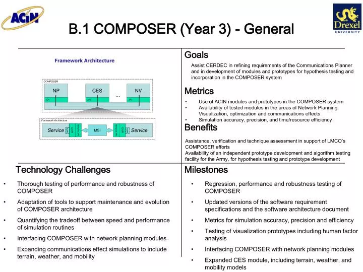
B.1 COMPOSER (Year 3) - General Assist CERDEC in refining requirements of the Communications Planner and in development of modules and prototypes for hypothesis testing and incorporation in the COMPOSER system • Use of ACIN modules and prototypes in the COMPOSER system • Availability of tested modules in the areas of Network Planning, Visualization, optimization and communications effects • Simulation accuracy, precision, and time/resource efficiency Assistance, verification and technique assessment in support of LMCO’s COMPOSER efforts Availability of an independent prototype development and algorithm testing facility for the Army, for hypothesis testing and prototype development Thorough testing of performance and robustness of COMPOSER Adaptation of tools to support maintenance and evolution of COMPOSER architecture Quantifying the tradeoff between speed and performance of simulation routines Interfacing COMPOSER with network planning modules Expanding communications effect simulations to include terrain, weather, and mobility Regression, performance and robustness testing of COMPOSER Updated versions of the software requirement specifications and the software architecture document Metrics for simulation accuracy, precision and efficiency Testing of visualization prototypes including human factor analysis Interfacing COMPOSER with network planning modules Expanded CES module, including terrain, weather, and mobility models
Assist LMCO in the ongoing evolution of the requirements, architecture, and testing of COMPOSER. B.1.1 COMPOSER (Year 3): Requirements, Architecture, & Testing THIS IS PART OF THE M&S FOR COMPOSER EFFORT FOR YEAR 3 – SEE QUAD CHART B.1 • Software bugs found/repaired. • Test code coverage statistics. • Number of features implemented. • LMCO receives assistance in three ongoing tasks related to the development of COMPOSER. • Detect drift between the documented requirements & features in the Software Requirements Specification and the implemented COMPOSER system. • Identify inconsistencies between the documented Software Architecture and the implemented COMPOSER system. • Predict whether the COMPOSER implementation will operate as expected under a variety of scenarios. • Quarterly updates of Software Requirements Specification (SRS) document. • Quarterly updates of Software Architecture document. • Quarterly updates of the Software Test Plan document. This document will include a report on tested features and bugs found to date.
THIS IS PART OF THE M&S FOR COMPOSER EFFORT FOR YEAR 3 – SEE QUAD CHART B.1 B.1.2 COMPOSER (Year 3): - Development of Waveform Models for Communication Effects Simulator Add support for additional waveform models in the Communications Effects Simulator (CES) of COMPOSER. • Computational complexity • Modularity and extensibility of object oriented waveform abstraction Greater support in CES of COMPOSER for a variety of different legacy and next-generation waveforms • Physical Layer link abstraction • Support for diverse signalling technologies (e.g., radio frequency, free space optical) and adaptive signalling techniques (e.g., link adaptive modulation, dynamic spectrum allocation) • Generalized waveform abstraction hierarchy to allow for ease of code development and potential for evaluation of new military waveform design evaluation • Needs discernment for new signaling technology and techniques to be added to Communication Effects Simulator • "Abstracted" waveform simulation architecture • Detailed performance analysis • Test and demonstration
THIS IS PART OF THE M&S FOR COMPOSER EFFORT FOR YEAR 3 – SEE QUAD CHART B.1 B.1.3 COMPOSER (Year 3) - Development of Multi-Fidelity Physical Layer Propagation Model Add support for multi-fidelity physical layer propagation models to support the faster-than-real-time requirements of COMPOSER • Simulation run-time • Computational complexity Greater support in CES of COMPOSER for intelligent, dynamic switching between library of physical layer propagation models • Physical layer propagation models must be adapted to accommodate the faster-than-real time run-time requirements of COMPOSER • Algorithm must be developed to dynamically switch between wireless propagation models in response to changing run-time and model performance (e.g. network size, specifications • Physical layer propagation model library report • Preliminary model-switching algorithm development • Report comparing/validating multi-fidelity model approach using conventional wireless propagation techniques • Final report with results from different operational tests (e.g., networks of varying size, simulation time budgets)
THIS IS PART OF THE M&S FOR COMPOSER EFFORT FOR YEAR 3 – SEE QUAD CHART B.1 B.1.4 COMPOSER (Year 3): Communication Effects Simulator (CES) Model Field Verification Validate physical layer propagation models and waveform abstraction used in the Communication Effects Simulator (CES) of COMPOSER • Physical layer model accuracy/precision • Refinement of models currently used in the CES Field validation of unique physical modeling assumptions made to develop CES • Use of Military-provided communication handsets along with specialized channel probing equipment to validate multi-fidelity, faster-than-real time physical layer propagation model used by the CES in COMPOSER • CES computer model enhancement based upon field measurement results in representative environments (e.g., urban, rural, subterranean) • Needs discernment of handset(s) / waveform(s) for field verification • Identification of representative test environments • Field-testing plan • Report on field-testing results and model verification/refinement
THIS IS PART OF THE M&S FOR COMPOSER EFFORT FOR YEAR 3 – SEE QUAD CHART B.1 B.1.5 COMPOSER (Year 3) - Realistic Warfighter and Combat Vehicle Modeling Complement existing far-field Physical layer models in the Communication Effects Simulator (CES) of COMPOSER with near-field models of personnel and vehicles • Physical layer model accuracy/precision • Refinement of models currently used in the CES • More realistic physical layer propagation models • Critical step in extending CES applicability to soldier/vehicle-level propagation channels • Incorporate near-field electromagnetic models of personnel and vehicles into the physical layer models used by COMPOSER • Develop library of near-field structures (e.g. personnel, vehicles, towers) that can be used to better predict communication link performance • Needs discernment of radio platform(s) and vehicle(s) to be included in modeling procedure • Identification/development of computational electromagnetics simulator • Performance evaluation of developed models in practical CES experiments • Final report on results and physical layer model refinement
THIS IS PART OF THE M&S FOR COMPOSER EFFORT FOR YEAR 3 – SEE QUAD CHART B.1 B.1.6 COMPOSER (Year 3): GPU-based Simulation for COMPOSER Exploit Commercial GPU Stream Processor for Real-time Terrain Reasoning Real-time Computational Simulation for M&S for Communications Size and scale of models simulated Fidelity of models and accuracy of results Improved warfighter networking Adapting GPU techniques to modeling and simulation of communications in “on the move” networks Atmospheric transport models Vehicle dynamics Wide area sensors Petabyte Urban Terrain Databases GPU for simulation background study Develop testbed for analysis of existing algorithms and techniques Initiate collaboration with leading researchers in GPUs (Manocha @ UNC-CH)
THIS IS PART OF THE M&S FOR COMPOSER EFFORT FOR YEAR 3 – SEE QUAD CHART B.1 B.1.7 Composer (Year 3): Network protocol stack abstraction for fast and accurate simulation Identify simplifications of network protocols to ease the computational burden of protocol simulation while minimizing the loss in model fidelity. Seek protocol simplifications that reduce simulation running time but yield performance measurements on par with accepted full-scale network simulators, e.g., OPNET. Reduced simulation computational complexity permits the field engineer to run longer, more accurate simulations on large scale networks. • MANET protocol simplifications at PHY, MAC, NET, TRA, APP layers • Plug and play network simulation architecture • Network performance metric sensitivity analysis "Abstracted" network simulation architecture Proposed network protocol simplifications Detailed sensitivity analysis Test and demonstration
THIS IS PART OF THE M&S FOR COMPOSER EFFORT FOR YEAR 3 – SEE QUAD CHART B.1 B.1.8 Composer (Year 3): "Perfect" simulation of MANET node mobility Simulation of MANETs requires initial placement of nodes. This placement may induce a transient in the simulation that will affect network performance measurements. Perfect simulation eliminates the transient by identifying the steady state distribution of node locations. Measure the impact of initial node placement distribution on network performance, e.g., "speed decay" pictured at left. Study the duration of the simulation transient as a function of network size. Knowledge of simulation transients and their impact. Identification of how to remove transients from simulation. The graphs show the average speed of nodes versus time in MANETS using random waypoint mobility model and simulate correctly speed decay over time There is a firm mathematical framework for identifying the stationary distribution of a broad class of movement models on a broad class of stationary topologies. The primary technical challenge is extending this analysis to military MANET movement models. The impact of simulation transients on military MANET mobility models and the scaling of transient duration in network size will be quantified. Mathematical model of military MANET mobility. Identification of steady state distribution of mobility model. Simulation of mobility model and study of transient impact. Simulation study of transient duration as a function of network size.
THIS IS PART OF THE M&S FOR COMPOSER EFFORT FOR YEAR 3 – SEE QUAD CHART B.1 B.1.9 Composer (Year 3):Network Visualization: Coping with Complexity Identify, invent, implement and test techniques for simplifying and visualizing complex graph structures that represent communication networks, as well as complex terrain datasets Time to plan and deploy a network Size of network/scenario to be displayed Interactive display speeds Improved user productivity and effectiveness Increased and optimized display of complex communication data 1542 node graph simplified to a 39 node graph using the FADE algorithm Development of algorithms that display complex graph structures in comprehensible formats Development of algorithms that simplify complex network graphs while maintaining the fundamental high-level structure of the network Development of algorithms that effectively simplify and organize terrain models into efficient data structures for rapid adaptive display Comprehensive survey of state of the art in visualizing and simplifying complex graph structures – including abstraction-based, distortion-based and zoom-based techniques, as well as graph decimation and reduction algorithms Comprehensive survey and assessment of relevant technology in advanced level-of-detail methods for processing and displaying large-scale terrain datasets Software demonstration of graph and terrain simplification/visualization algorithms using COMPOSER-specific network configurations.
Figure 1. An example of a critical path analysis of user behavior Figure 2. A behavior graph of a COMPOSER use-case scenario THIS IS PART OF THE M&S FOR COMPOSER EFFORT FOR YEAR 3 – SEE QUAD CHART B.1 B.1.10 Composer (Year 3): Human Factors for Composer Review current protocols for network planning. Identify human factors issues associated with COMPOSER Usability analysis of COMPOSER. Verbal protocol analysis of users working with COMPOSER Reduce design-based errors Improve COMPOSER usability Comprehensive review of current methods for network planning. Development of new usability testing protocols for COMPOSER. Analysis of quantitative and qualitative results from COMPOSER user testing. Document existing protocols for network planning for human factors analysis Develop new protocols for measuring and analyzing usability in COMPOSER Develop user testing methods that closely reflect realistic use of COMPOSER
THIS IS PART OF THE M&S FOR COMPOSER EFFORT FOR YEAR 3 – SEE QUAD CHART B.1 B.1.11: Composer (Year 3): Enhancing COMPOSER’s Visualization Capabilities with GPUs Identify, invent, implement and test techniques based on Graphics Processing Units (GPUs) that will enhance COMPOSER’s visualization capabilities Time to plan and deploy a network Size of network/scenario to be displayed Interactive display speeds Improved user productivity and effectiveness Increased and optimized display of complex communication data ATI Radeon 9700 and NVIDIA Quadro FX4500 GPUs Comprehensive survey of state of the art in GPU systems, languages and algorithms Development and analysis of GPU-based visualization algorithms that may be utilized by COMPOSER Software demonstration of GPU-based visualization algorithms that display complex communications scenarios. Benchmarking of display performance of GPU and non-GPU COMPOSER visualization algorithms Mapping COMPOSER visualization algorithms into GPU programming languages Optimization of COMPOSER visualization algorithms within a GPU architecture Determination of GPU architecture-specific features, behaviors and bottlenecks Identifying optimal GPU architecture and language to meet COMPOSER’s visualization requirements
B.2 Modeling and Simulation in Support of Communications, Year 2 Study node mobility (position agility) and cognitive radio (frequency agility). Improve simulation efficiency by removing transients (perfect simulation) and reducing simulation time (quick simulation). Increase in network performance achievable through node mobility and cognitive radio. Decrease in simulation time achievable through quick and perfect simulation techniques. Increase in network performance through sophisticated resource allocation. Increase in simulation efficiency through sophisticated simulation techniques. • An optimization algorithm that exploits position and frequency agility to maximize network performance. • A simulation algorithm that avoids initial transients to achieve perfect simulation. 3. A simulation algorithm that uses importance sampling to increase the occurrence of rare events. Year 1 development is focused on defining performance metrics relevant to assessing network health, as well as optimization techniques applicable to maximizing those metrics given available resources. Year 2 development will optimize network design when network resources have additional degrees of freedom (location agility and frequency agility). Year 2 development will also address the problem of increasing the accuracy and speed of network simulation (through “quick simulation” and “perfect simulation” techniques).
THIS IS PART OF THE M&S FOR COMMUNICATIONS EFFORT FOR YEAR 2 – SEE QUAD CHART B.2 B.2.1 M&S for Communications: Mobile Access Points for Coverage Maximization Devise a dynamic access point placement algorithms for mobile networks in operation Implement algorithm in a network of hand held units with mobile base stations Measured improvement in coverage area and network connectivity under mobility and path restrictions Robustness to unit loss and to incremental unit moves Two robotic APs are initially located in close proximity (left), which ensures connectivity but doesn’t maximize coverage area. The two APs automatically position themselves at intersections at an appropriate distance from one another (right). The final positions maintain connectivity and maximize coverage area. Increased connectivity of mobile networks in dynamic operations Increased network performance (throughput, latency, dropped packets) • An optimization algorithm that calculates the optimal location of APs under physical and accessibility constraints • A path calculation and navigation algorithm to move mobile units that carry the APs to these optimal locations. • A test bed, using physical robots and an ad-hoc mobile communication network, to demonstrate the operation of an automatic AP placement system in several different environments (outdoors, dense urban environments, inside buildings). Development of situation-aware adaptive distribution of APs and “hot spots” in wireless networks Base station optimal placement Adaptation of station shifting locations to needs of combatants/rescuers in order to provide optimal or near-optimal coverage at all times. Implementation through a physical system that is rugged, reliable, easy to use, and highly portable. Design of secure mobile unit path to maximize coverage and avoid forbidden areas (path planning)
THIS IS PART OF THE M&S FOR COMMUNICATIONS EFFORT FOR YEAR 2 – SEE QUAD CHART B.2 B.2.2 M&S for Communications (Year 2): Importance sampling for MANET simulation Importance sampling (IS) is a "variance reduction" technique to improve the computational complexity of "rare event“ simulation. We bias the simulation to make rare events more common, then correct for the bias. Great reductions in computational effort may be achieved by applying IS to MANET simulation. The IS gain is the ratio of the number of simulations required by conventional Monte Carlo (MC) estimators over the number required with an IS estimator. The IS distribution may be optimized to maximize the IS gain (see figure). Benefits in MANET simulation is in simulating "rare events" like network failure and disconnection. Left: estimated number of simulations versus the biasing parameter for the estimation of the tail of a Poisson random variable. Right: estimated speedup in simulation time versus the biasing parameter. Simulation of MANET rare events is important to quantify in a statistically rigorous manner, but the computational effort required is prohibitive. IS offers a well established technique to obtain these estimates in a cost-effective manner. Identification of appropriate MANET "rare events", e.g., network failure, islanding, and disconnection. Conventional Monte Carlo (MC) estimation of these parameters. Identification and optimization of appropriate Importance Sampling (IS) distributions. Quantification of IS gain for specified bound on relative error and confidence level. Implementation of conventional Monte Carlo (MC) simulation for MANETs. Implementation of importance sampling (IS) simulation for MANETs. Report studying reduction in computational effort and choice of IS distributions. Lockheed Martin ATL indicated interest in participating in this project, including investment of LMCO-ATL IRAD funds
B.3 TTW (Year 2): Field-Testing of RFID Authentication System Evaluate RFID authentication system in combination with Time Domain Inc. Soldier Vision STTW system in complex, real-world environment Eliminate false negatives for authentication Authenticate thru 15 most common wall types Optimization of authentication system for field operations Real-world evaluation of system limits Compensating for reflections and scattering from multiple wall architectures Use software to compensate for environmental factors: ambient temperature, humidity, precipitation Design packaging that can withstand drops and impacts Evaluation of performance thru many wall types Evaluation of wall material penetrate depth Demonstration of accurate multi-wall (3) ranging and authentication Environmental chamber test results Impact test results Field performance at testing range
B.3.1 TTW (Year 2): Soldier Geolocation in GPS-Inaccessible Areas THIS IS PART OF THE THROUGH THE WALL EFFORT FOR YEAR 2 – SEE QUAD CHART B.3 Map soldiers in locations that are outside the range of GPS signals (e.g. inside buildings, underground, etc.) Position accuracy Ability to work through different types of structural materials (concrete, brick, drywall, etc.) Global measurement of position at all times and in all environments Selecting frequencies that are non-interfering with current telecommunications Wide range of frequency penetration: standard building materials span many types, including brick, adobe, cinder block, reinforced-concrete, wood, etc. Compensating for reflections and scattering from multiple wall architectures Accurately triangulating position through walls Synchronizing with GPS system Evaluation of frequency ranges that penetrate building materials Design of portable transceivers of geolocation Demonstration of geolocation while off the GPS grid Results of field tests on performance of non-GPS geolocation system
B.3.2 TTW (Year 2): Integrated Authentication and Thru-Wall Personnel Identification Device (PID) THIS IS PART OF THE THROUGH THE WALL EFFORT FOR YEAR 2 – SEE QUAD CHART B.3 Integrate ability to authenticate soldier identity with ability to sense presence of personnel thru walls in a single standalone device Simultaneous identification of multiple personnel thru a range of wall types Authentication of friendly and unknown personnel on display Identification and authentication will occur in one portable device Increased number of identifications Ability to penetrate more building materials than current STTW system Select Ultra Wideband transceivers with good wall penetration Select interference resistant communication technique Increase thru-wall imaging range from 10 meters (current commercial limit) to 50 meters Develop passive RFID tags that identify personnel when in range of PID of but require no power source Demonstrate proof-of-concept integrated device Evaluation of frequency ranges that penetrate building materials and provide RFID interaction Identification of person thru a reinforced concrete wall Authentication of friendly/non-friendly person thru a reinforced concrete wall Comparison to Time Domain Inc. Soldier Vision Results of field tests on PID system
B.4 Intelligent Agents (Year 2) : Agent Reference Model for Network-Centric C2 Applications Develop a reference model for Agent-based systems. Configure a testbed with existing DoD-relevant Agent Systems Penetration into DoD programs and acquisition activities • Support for C2D programs • CORE, RUS, SoSCOE, NEBC • Enable transition of Agent technologies Software comprehension of agent platforms Static analysis of agent platforms and agent-based applications Dynamic analysis of agent-based applications Testbed deployment
THIS IS PART OF THE Intelligent Agents EFFORT FOR YEAR 2 – SEE QUAD CHART B.4 B.4.1 Metrics for Assessing Quality of Intelligent Agent Frameworks Use software engineering code metrics to assess the reliability, maintainability, security, and efficiency of the code that implements agent-based frameworks. class SafeSort { static void sort ( int [] intarray, int order ) throws SortError { int [] copy = new int [intarray.length]; for (int i = 0; i < intarray.length ; i++) copy [i] = intarray [i] ; try { Sort.bubblesort (intarray, intarray.length, order) ; if (order == Sort.ascending) for (int i = 0; i <= intarray.length-2 ; i++) if (intarray [i] > intarray [i+1]) throw new SortError () ; else for (int i = 0; i <= intarray.length-2 ; i++) if (intarray [i+1] > intarray [i]) throw new SortError () ; } catch (SortError e ) { for (int i = 0; i < intarray.length ; i++) intarray [i] = copy [i] ; throw new SortError ("Array not sorted") ; } } } Code structure metrics Code complexity metrics Code size metrics Code security metrics Evaluate the quality of the code that implements the intelligent agent frameworks upon which important software is constructed. Mine the academic literature for appropriate software metrics. Develop tools that can compute these metrics on source code. Determine the weight each metric has on the assessment of any intelligent agent framework. Software metrics survey. Implementation of metrics calculators. Integration of metrics calculators with source code analysis tools. Evaluation of the metrics and tools on various intelligent agent frameworks such as EMMA, COUGAAR,and JADE.