Download

1 / 45
450 likes | 458 Views
Chapter 8 Modulators and Demodulators.

E N D
Chapter 8 Modulators and Demodulators
Modulation is the modification of a high-frequency carrier signal to include the information present in a relatively low frequency signal. This is necessary because radio wave propagation is more efficient at higher frequencies and smaller antennas can be used. A larger bandwidth can be obtained at higher frequencies, enabling many information-containing signals to be multiplexed onto one carrier and sent simultaneously. • Frequency conversion, modulation and detection are common tasks performed in a communication circuit. Frequency Mixers • The most commonly used device for frequency modification is the mixer. It is basically a multiplier • The output consists of the sum and difference of the two input frequencies, one of which is the desired component. The other will be filtered out. This combination of a mixer and filter to remove an output frequency is known as single-sideband mixer. • There are 2 main classes of mixers -- nonlinear or switching-type.
Switching-Type Mixers • One or more switches, realized by diodes or transistors, will function as the time-varying circuit elements.
For ideal center-tapped transformer, the voltages will be indicated as below • The local oscillator VL is a constant- amplitude signal. VL >> Vi so that D1 is on when VL is positive and D2 is on when VL is negative. Thus
The output consists of the local oscillator plus Vi switched by 180 at the frequency of the local oscillator. If the switched form of Vi is represented by Vi* then • The Fourier series for P(t) and Vi* are • If Vi is a sine wave then • Since the mixer output consists of the local oscillator signal plus an infinite number of additional frequencies created in the mixer. The output frequencies in addition to the upper and lower sidebands are called spurious. The desired component is obtained by filtering.
The preceding analysis assumed that the local oscillator signal was much larger than the input signal and sufficiently large to turn on the diodes instantly. Deviations from these assumptions will result in distortions in the desired frequency component. • A disadvantage of the circuit above is that VL appears in the output. If the oscillator frequency is much larger than the input frequency, then the desired mixing product may be close to the oscillator freq. and will be difficult to separate by filtering. In the new circuit below
The local oscillator signal does not appear in the output. For ideal transformer the voltages are shown below
If VL is positive and much larger than Vi than both diodes are conducting . The local oscillator current balance out in the output transformer Vo=Vi. If VL is negative, the diodes will be open and the output signal will be zero. Thus • If Vi is a sine wave Vi=Vsinit, the output is • The output of this mixer differs from the previous one in that it does not contain the local oscillator signal but it does contain a signal at the same frequency as the input signal. Four Diode Switching Type Mixer • The construction of this type of mixer is shown below
Neither the local oscillator signal and the input signal appears at the output. If the local oscillator, VL, is positive, then diodes D2 and D3 will conduct and the equivalent circuit is shown below • rd is the diode on resistance. The loop equations are • Thus • If the local oscillator signal is negative, diodes D1 and D4 conduct and the equivalent circuit is
In this mixer the output voltage is proportional to the input voltage is switched at the local oscillator frequency. Therefore if • then • A double-balanced mixer with perfectly matched diodes and ideal transformer coupling will generate the upper and lower sidebands plus an infinite number of spurious frequencies centered on odd harmonics of the local oscillator frequency. Their excellent performance is due in part to modern fabrication techniques to construct closely matched diodes. High frequency Schottky barrier diodes are often used today.
Conversion Loss • Mixer conversion loss is defined as the ratio of output power in one sideband to signal input power. It is a most important mixer parameter, particularly for the receiver. • From Fig. 12.13, and the load impedance seen by Vi is • Normally RL>>rd so the input will be matched for maximum power transfer if RL=Rs. Under this condition Vi=Vs/2 and • The output voltage in on sideband, for RL>>rd, is the output power is • So the conversion gain of the double-balanced mixer is • The conversion loss is • For an ideal double-balanced mixer matched to the source impedance, and ignoring the power lost in the transformer and switching diodes, approximately 40% of the signal input power will be transferred to the output.
For the single-balanced mixer, the output voltage of one sideband is • If the port is matched for maximum power transfer • The power gain is . The conversion loss is 4 times (6 dB) larger than double-balanced mixer Distortion • As the mixer input signal power increases, it will reach the level at which it is larger than the local oscillator. • The input signal then assumes the switching role, and the output power becomes proportional to the local oscillator power. Since the local oscillator is constant the output power will be constant.
Intermodulation Distortion • Consider a diode-ring mixer with a resistance R in series with each diode as shown below • The purpose of the additional resistors will become clear once the IMD is determined. • If the local oscillator power is sufficiently large, the circuit during either half-cycle is as shown below
The diode current then consists of a constant component I, due to the local oscillator, and a small component i, due to the input signal. The diode current is described by where Vd is the voltage drop across the diode and VT=kT/q • The input signal Vi causes a signal current 2i to flow through the load. Because of the circuit symmetry one-half flows through each diode. That is • The currents are shown in Fig. 12.18. The voltage equations are • adding the two equations we get • and since the relation between input voltage and diode current is
This can be expanded for i<<I to • The even order terms cancel out so • Since the first term of the power series is not zero, the series can be inverted
Square-law Mixers • The square-law characteristic is approximated by several electronic devices which square the sum of two sine waves • An ideal square-law device will provide the upper and lower sidebands, together with a dc component and the second harmonic of both input waveforms. The circuit is frequently used at microwave frequencies for down conversion to the lower side-band, which is at a lower frequency than either of the input signals. A simple square law mixer is shown below
Schottky barrier diodes are typically used for high speed applications. • At lower frequencies this form of the diode mixing is normally not used because of the large conversion loss. Transistors mixers are preferred because they can provide conversion gain. Transistors are often used to approximate the square-law characteristic. The input and local oscillator signal voltages are applied to the transistor so that they effectively add to the dc bias voltage to produce the total gate-source of base-emitter voltage. The composite signal is then passed through the device nonlinearity to create the sum and difference frequencies. BJT Mixers • This is illustrated in the figure
The base to emitter voltage is where VDC is the base-to-emitter bias voltage. The collector current in a bipolar transistor is described by (Vbe > 0) • If then the current can be expanded in a series of modified Bessel functions as • where and In is the nth-order modified Bessel function. • The collector current consists of a dc component IC, components at both the input and oscillator frequencies, components at the frequencies , and an infinite number of high-frequency components. The amplitude of either the upper or lower-sideband component is
The local oscillator voltage amplitude is constant and V2>>V1, then the collector direct current will not vary with changes in the amplitude of the input signal since . • The mixer should have a linear response to changes in the amplitude of the input amplitude. The ratio is given as . • So if the input amplitude is sufficiently small the mixer upper- and lower-sideband outputs will be a linear function of the input signal. For y<0.4 (V1<10.5 mV) the response will be within 2 percent of a linear response. The amplitude of the sideband current is
FET Mixers • If an FET is operated in its “constant-current” region, the idealized FET current transfer characteristics is the square-law relation where Vgs is the gate-to-source voltage and Vp is the transistor pinch-off voltage. Because of the square-law characteristic, the FET will not generate any harmonics higher than second-order intermodulation distortion. However, in reality, the transfer characteristic deviates from the idealized version, version and some intermodulation distortion will be produced. Still, a properly biased and operated FET mixer will produce much smaller high-order mixing products than a bipolar transistor. This is one reason why an FET is usually preferred to a bipolar transistor mixer. • The FET also provides at least 10 times as great an input voltage range as the BJT. The following figure illustrates an FET mixer circuit. The drain current is
where VDC is the gate-to-source bias voltage (or VGS-VT for a MOSFET). If the applied signals are sine waves • then the output current is • The amplitude of the sum and difference frequencies is • where K3/Vi is referred to as the conversion transconductance gc. In general the device with the lowest pinch-off voltage has the highest gain, and the conversion transconductance is directly proportional to the amplitude of the local oscillator signal.
It would also appear that FETs with high IDSS are preferred, but IDSS and Vp are related. It is usually the case that devices selected for high IDSS also have a high Vp and a lower conversion transconductance that low- IDSS devices. Since the device is to be operated in the constant-current region, VL must be less than the magnitude of the pinch off volgate. If then K3=Vi IDSS/2Vp and the sideband current is • Since for a JFET the transconductance is • The conversion transconductance is one-fourth the small-signal tansconductance evaluated at Vgs=0 (provided VL=Vp/2). For a MOSFET it can be shown that the conversion conductance cannot exceed 1/2 of the transconductance of the device when it is used as a small-signal amplifier. • Although the conversion transconductance is smaller than the small-signal transconductance, it is large enough that the circuit can be operated as a mixer with power and voltage gains. This is an important difference from the diode-switching mixer.
An FET mixer is capable of producing lower intermodulation and harmonic products than a comparable bipolar or diode mixer. Also, an FET mixer operating a high level has a larger dynamic range and greater signal-handling capacity than a diode mixer operated at the same local oscillator level. However, the noise figure of FET mixers is currently higher than that of diode mixers. The best intermodulation and cross-modulation performance is obtained with the FET operated in the common-gate configuration, where the input impedance is much lower than that for the common-source configuration. • The figure below illustrates double balanced mixer in which the FET transistors are operated in the common-gate configuration. The push pull output cancels the even-order output harmonics.
The dual-gate MOSFETs is often used as a mixer. A typical dual-gate MOSFET mixer circuit is shown below • If the input signals are sinusoidal, the output will contain frequency components at both the sum and difference frequencies. Several other frequency components are also present in the output. The magnitude of either the sum or difference frequency is proportional to
so the conversion gain is proportional to the magnitude of the local oscillator voltage. For maximum conversion gain, the local oscillator amplitude should be selected so that it drives the gate just to the point of transistor saturation. • The input signal is normally connected to the lower (closest to the ground) input gate terminal and the local oscillator signal to the upper gate. If the input is connected to the upper terminal, then the drain resistance of the lower transistor section appears as a source resistance to the input signal. The source resistance will reduce the voltage gain at the collector. Also, the connection has a larger drain-to-gate capacitance with a lower bandwidth than is attainable when the input signal is connected to the lower gate. The device is usually biased so that both transistors are operating in their nonsaturated region. • The small-signal drain current is • The drain current can be written as • Since the drain current contains the product of the 2 signals, the dual-gate MOSFET can be used as a mixer when both transistors are operated in the linear region.
Amplitude and Phase Modulation and Demodulation • Amplitude modulation (AM) is the process of varying the amplitude of a constant frequency signal with a modulating signal. An amplitude-modulated wave can be mathematically expressed as where g(t) is the modulating signal and c is the carrier frequency. Normally the modulating signal varies slowly compared with the carrier signal frequency. Conventional AM is in the form of where m is the modulation factor and is normally less than 1. Consider a simple modulating signal: • The frequency spectrum of the modulated signal is shown
The equation above shows that for m<1 the amplitude of the carrier is at least twice as large as the amplitude of either sideband component, so at least 2/3 of the signal power will be in the carrier and at most 1/3 in the 2 sidebands. Because the carrier does not contain any information, it is often removed or suppressed in the signal which is referred to as a double-sideband (DSB) suppressed-carrier signal. The carrier component is not present in the DSB signal. However, as the waveform gets more efficient in terms of power-to-information content, the detection method gets more complex. Some means of recovering the carrier component is needed for the detector to recover the amplitude and frequency of the modulating signal. The DSB signal, although more efficient in terms of transmitted power, still occupies the same bandwidth as a normal AM signal. Since both sidebands contain the same information, one sideband can be removed, resulting in a single-sideband-signal (SSB).
Amplitude Modulators • Full-carrier double-sideband amplitude modulation is achieved either modulating the oscillator signal at a relatively low power level and amplifying the modulated signal with a cascade of amplifiers or by using the modulating signal to control the supply voltage o fthe power amplifier. Both methods are illustrated below
The power requirements of the modulator and modulating signal can be estimated by considering the power in an amplitude-modulated waveform . The peak power is so if the maximum modulation index is unity, The modulator must be designed to handle 4 times the average carrier power with 100% modulation; the output power will be 4 times the carrier power. • The diode mixer can be used to realize low-level modulation. If VL is a sine wave and if a low-pass filter is added to the output with a bandwidth of then the output will be • . Since the low-pass filter removes the higher-frequency component, the modulation index of the resulting AM waveform is . This particular amplitude modulator functions well only for low indices of modulation. • Both FET and BJT mixers can function as amplitude modulators with a relatively high modulation index. The final amplifier will need to be linear. The output will then be linearly related to the input provided
the amplifier output circuit is not current-limited. • The most frequently used method of amplitude modulation at high power levels is to modulate the supply voltage to the power amplifier, as shown in Fig. 12-27b. In the figure below the modulating signal is applied in series with the dc supply voltage, so the total low-frequency supply for the transistor is
For Class C power amplifiers the amplitude of the output signal under saturation-limited conditions equals the power supply voltage. Therefor changing the transistor supply voltage modulates the output signal amplitude proportionally, and the output voltage becomes . For 100% modulation the peak value of the voltage Vm(t) must equal VCC. The total output power is . The unmodulated carrier power is supplied by the power supply. The remaining power must be furnished by the modulator. One reason that output modulation has been the most frequently used method is that collector modulation results in less intermodulation distortion. • All the information in an AM wave is contained in one sideband. It is possible to eliminate the other sideband without loss of information; thus the required transmitter power is reduced to one-third of that previously required. • The simplest method of SSB generation is to generate the DSB signal using a double-balanced modulator and then remove one of the
sidebands with a filter. A block diagram of this form of SSB is shown below • Another technique know as phasing method is shown below:
Here both the modulating signal and the carrier signal are processed through phase splitters, which each generate two signals 90 out of phase with each other. The summing network output is the desired SSBsignal. The phasing method has the advantage of not requiring the sharp cutoff filters of the filtering method of SSBgeneration, but it is difficult to realize a broadband phase-shifting network for the lower frequency modulating signal. Demodulators • AM detection can be divided into synchronous and asynchronous detection. Synchronous detection employs a time-varying or nonlinear element synchronized with the incoming carrier frequency. Otherwise the detection is asynchronous. The simplest asynchronous detector, the average envelope detector, is described below:
Average Envelope Detectors • A block diagram of the average envelope detector is shown in the fig. • The rectifier output • can be written as • If S(t) is periodic with a frequency c, since • If S(t) is the AM wave described by
If the low-pass filter bandwidth is chosen to filter out the component at c and all higher harmonics, the output will be which is a dc term plus the modulating information. • Two additional points will be made to further describe the operation of the envelope detector. First, consider the case where • The • The output will contain a term at the frequency , which must also be removed by the low-pass filter. This is not possible if m is close to c. To ensure this distortion does not occur the max modulating frequency should be and the corresponding low-pass filter bandwidth B must be selected so that • This is only possible if m is not greater than 1, and the carrier term is present. Average envelope detection will only work for normal AM with a modulation index less than 1. However, if a large carrier component Acosct is added to the SSB signal, the resultant signal can also be detected with an envelope detector.
A simple diode envelope detector circuit is shown in the figure below • It is assumed here that the input signal amplitude is large enough that the diode can be considered either on or off, depending upon the input signal polarity. The diode can then be replaced by a open circuit when it is reverse-biased and by a constant resistance when it is forward-biased. The series capacitor Cc is included to remove the dc component. The purpose of the load capacitor C in the circuit is to eliminate the high-frequency component from the output and to increase the average value of the output voltage. The effect of the load capacitor can be seen from the figure below
which illustrates the input and the output signal waveforms of a diode detector. As the input signal is applied, the capacitor charges up until the input waveform begins to decrease. At this time the diode becomes open-circuited and the capacitor discharges through the load resistance RL as where Vp is the peak value of the input signal, and the diode opens at time t=0. The larger the value of capacitance used, the smaller will be the output ripple. However, C cannot be too large or it will not be able to follow the changes in the modulated signal. The time constant is often selected as
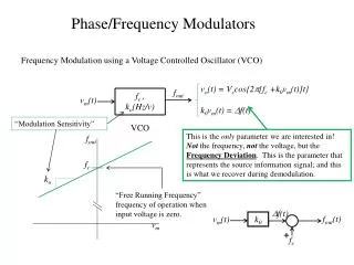
Angle Modulation • Information can also be transmitted by modulating the phase frequency. Angle modulation occupies a wider bandwidth, but it can provide better discrimination against noise and other interfering signals. An angle-modulated waveform can be written as where (t) representing the angle modulation. Angle modulation can be further subdivided into phase and frequency modulation, depending on whether it is the phase or the derivative of phase that is modulated. Frequency modulation and phase modulation are not distinct, since changing the frequency will result in a change in phase and modulating the phase also modulates the frequency. Angle Modulators • Frequency modulation can be achieved directly by modulating a VCO (direct FM) or indirectly by phase-modulating the RF waveform by the integrated audio input signal (indirect FM). Another method of FM is to use a phase-locked-loop as shown below
The output in response to the modulating signal Vm is • where Kd is the phase-detector gain constant and Ko is the VCO sensitivity (Hertz per volt). In the steady state, the output phase will be proportional to the modulating voltage. So the PLL can serve either as a phase modulator or, if VM is the integral of the modulating signal of interest, as a frequency modulator.
FM Demodulators • The same type of circuitry is used for detecting both types of angle modulation, and we will refer to either process as FM detection. FM detectors are often referred to as frequency discriminators. • The ideal FM detector produces an output voltage that changes linearly with changes in the input frequency as shown • The output voltage is usually 0 at the carrier frequency. Any deviation from the linear characteristic distorts the detected waveform. Amplitude modulation caused by noise can also cause distortion in the recovered signal. Limiting circuitry is usually included in FM detector to reduce the amount of amplitude modulation. The transfer characteristic of an ideal
limiter is shown below The limiter output is restricted to the values that depend only on the sign of the input. A single stage differential-pair limiter is shown
The circuit gives a close approximation to the ideal limiter characteristics. If the input signal is too small, several differential-pair stages may be cascaded in order for the output to be saturated. Integrated-circuit limiters frequently contain 3 cascaded stages. • An analytical basis of FM detection is obtained by considering the derivative of the FM signal • The derivative of an angle-modulated signal is an amplitude-modulated FM waveform. All the modulating information is contained in the amplitude of the differentiated waveform. Normally if so the amplitude modulation can be removed with an envelope detector. The output of the envelope detector will be proportional to , which is for a frequency-modulated waveform. If the output is then high-pass filtered to remove the constant term , the remainder will be proportional to the modulating signal. This technique has the disadvantage that any dc components in the modulating signal is lost.
The most often used circuit for realizing the differentiator is the single-tuned circuit. The frequency response of an ideal differentiator has a +90° phase shift, and the magnitude increases with increasing frequency at 6 db per octave. The frequency response of a simple tuned circuit will approximate this response at frequencies sufficiently below the circuit’s resonant frequency. • The frequency response magnitude of the parallel tuned circuit is • Values for Q and 0 for a parallel tuned circuit are, in which Rp, C and L and parallel to each other
The magnitude of the frequency response of the parallel resonant circuit is shown below • At frequency • provided c is close enough to 0 so that
Also if • The output consists of a constant term corresponding to c plus a component proportional to the frequency deviation . Balanced discriminators are often used to eliminate the constant term. A simplified balanced discriminator is illustrated below output is then which is proportional to the frequency deviation from the carrier frequency. The upper resonant cirucit is tuned to the frequency 0- c, and the output is proportional to c- . The differential