Download
1 / 22
220 likes | 295 Views
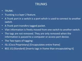
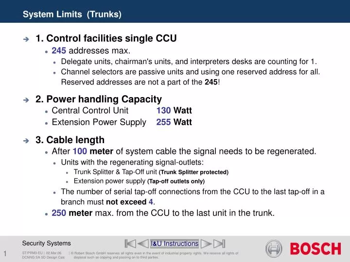
System Limits (Trunks). 1. Control facilities single CCU 245 addresses max. Delegate units, chairman's units, and interpreters desks are counting for 1. Channel selectors are passive units and using one reserved address for all. Reserved addresses are not a part of the 245 !

E N D
System Limits (Trunks) • 1. Control facilities single CCU • 245 addresses max. • Delegate units, chairman's units, and interpreters desks are counting for 1. • Channel selectors are passive units and using one reserved address for all. Reserved addresses are not a part of the 245! • 2. Power handling Capacity • Central Control Unit 130 Watt • Extension Power Supply 255 Watt • 3. Cable length • After 100 meter of system cable the signal needs to be regenerated. • Units with the regenerating signal-outlets: • Trunk Splitter & Tap-Off unit (Trunk Splitter protected) • Extension power supply (Tap-off outlets only) • The number of serial tap-off connections from the CCU to the last tap-off in a branch must not exceed 4. • 250 meter max. from the CCU to the last unit in the trunk. I&U Instructions DCNNG SA SD Design Calc
Power Consumption in Watt • Discussion Unit with fixed microphone 2.75 W • Discussion Unit 2.75 W • Discussion Unit with Channel selector 2.9 W • Discussion Unit Dual 2.8 W • Discussion Unit Dual with channel selector 3.15 W • Discussion Unit with voting 3.05 W • Discussion Unit with voting and channel selector 3.20 W • Concentus Chairman unit 4.2 W • Concentus basic unit 3.4 W • Concentus with channel selector 3.7 W • Concentus full function 4.2 W • Voting Unit 1.0 W • Dual Delegate Interface 4.5 W Inclusive all connected FM panels. I&U Instructions DCNNG SA SD Design Calc
Power Consumption in Watt • Interpreter’s Desk 3.6 W • Channel selector unit 0.9 W • Data distribution unit 2.0 W • Extension Power Supply 0.8 W • Trunk Splitter 1.3 W • Tap-Off Unit (Trunk Splitter Protected)1.4 W Watt value includes the 2 meter (6.5 ft.) unit-cable. • Audio Expander Analogue 7.6 W • Audio Expander Digital 6.0 W • Cobra net interface 10.5 W • Optical Network splitter 3.9 W • Fiber Interface (POF/GOF or GOF/POF) 4.6 W I&U Instructions DCNNG SA SD Design Calc
Trunk Tap-off 65 W 65 W 85 W 65 W 65 W 85 W 85 W 65 W 65 W 65 W 130 W 255 W 130 W Power handling capacities Central Control Unit Central Control Unit Extension Power Supply DCN-CCUB DCN-CCU DCN-EPS I&U Instructions DCNNG SA SD Design Calc
Max. all trunks: • 36 Interpreter desks • 100 Channel selectors or Central Control Unit 1 n 18 n 50 1 Cable length per outlet to the last unit 100M Max. number of units within 100M from CCU • Max. per trunk: • 18 Interpreter desks • 50 Channel selectors or I&U Instructions DCNNG SA SD Design Calc
Max. all trunks: • 36 Interpreter desks • 140 Channel selectors or Central Control Unit 1 n 18 50 1 TS 51 70 * * Max. Cable length 100m * Tap-off outlets. Max. number of units connected to the CCU • Max. per trunk: • 18 Interpreter desks • 70 Channel selectors or I&U Instructions DCNNG SA SD Design Calc
Max. all trunks: • 69 Interpreter desks • 150 Channel selectors or Trunk Tap-off Extension Power Supply 1 n 23 n 50 1 n 50 1 Cable length per outlet to the last unit 100M Max. number of units within 100M from EPS • Max. per trunk: • 23 Interpreter desks • 50 Channel selectors or I&U Instructions DCNNG SA SD Design Calc
Max. all trunks: • 69 Interpreter desks • 270 Channel selectors or Trunk Tap-off * * * * * Tap-off outlets. Max. number of units connected to the EPS • Max. per trunk: • 23 Interpreter desks • 90 Channel selectors or Extension Power Supply 1 n 23 50 1 51 90 LBB4114 50 1 51 90 LBB4114 Max. Cable length 100m I&U Instructions DCNNG SA SD Design Calc
Extension Power Supply Trunk-in Trunk-out ** * * * Tap-off outlets which regenerating the digital signal. Trunk Outlet & Tap-Off Outlets • For Trunk-cable splitting with regenerating the digital signal. Trunk Splitter & Tap-Off unit (trunk splitter protected) I&U Instructions DCNNG SA SD Design Calc
* * * Tap-off outlets with a limitation of 4,5 Watt. * * Using the Tap-Off unit (Trunk Splitter Protected) LBB4115 LBB4115 I&U Instructions DCNNG SA SD Design Calc
Central Control Unit Tap-off Trunk-line Trunk Splitter Tap-off Trunk-line Loop Through Tap-Off Limitations Extension Power Supply 1st Tap-off 2nd Tap-off 1st Tap-off 3rd Tap-off 2nd Tap-off 4th Tap-off 3rd Tap-off 5th Tap-off 4th Tap-off I&U Instructions DCNNG SA SD Design Calc
Central Control Unit Regenerative Tap-off Trunk Splitter Extension Power Supply Regenerative Tap-off Trunk Splitter Extension Power Supply Maximum Cable Lengths 250M I&U Instructions DCNNG SA SD Design Calc
Central Control Unit 10m (32.8ft.) 20m (65.6ft.) 50m (164ft.) Longest Extension Cable example • The length of cable used in a system has a direct influence on the load of a system. • The second in- line trunk- splitter has two extension cables connected to it, with lengths of 20 m and 50 m. • When determining the cable length of a Trunk-outlet or Tap-off outlet, the longest extension cable only is taken in to account. • Therefore, the total extension cable lengthfrom a single Trunk-outlet of the CCU is calculated as 10+50= 60 m (196.8 ft.) I&U Instructions DCNNG SA SD Design Calc
Central Control Unit 10x 5x 1 2 40m. Max. Cable length 100m 50m. 12x 12x * TS 15m. 12x 12x To EPS See next slide * TS Power calculation Example-1 LBB4114 Example DCNNG SA SD Design Calc
Trunk Tap-off Extension Power Supply 10x 10x 35m. 3 4 5 20m. 20x 20x 20m. 22x 15x * 40m. 20x 10x TS 20m. 15x 24x * Max. Cable length 100m TS Power calculation Example-2 LBB4114 LBB4114 Example DCNNG SA SD Design Calc
Cable correction graph I&U Instructions DCNNG SA SD Design Calc
System Limits (Optical) • 1. Maximum number of nodes is 63 • 2. Maximum number of optical devices is 16 • 3. Optical Plastic Fiber length is maximum 50 Meter • 4. Maximum Optical cable length is depending of the number of nodes in the system I&U Instructions DCNNG SA SD Design Calc
Number of nodes per optical unit • Basic Central Control Unit 0 • Central Control Unit 2 • Audio Expander LBB4402/00 1 • Digital Audio Expander 1 • CobraNet Interface 1 • Optical Network Splitter 1 • Fiber Interface POFGOF & GOFPOF 0 • Integrus Transmitter 4 channels 1 • Integrus Transmitter 8 channels 2 • Integrus Transmitter 16 channels 4 • Integrus Transmitter 32 channels 8 I&U Instructions DCNNG SA SD Design Calc
Fiber interface without address • The fiber interface is used to: • convert from plastic optical fiber (POF) cable to glass optical fiber (GOF) cable and vice versa. • cover distances of more than 50 m in the optical network. LBB4414/10 LBB4414/10 I&U Instructions DCNNG SA SD Design Calc
Nodes Cable lengths graph I&U Instructions DCNNG SA SD Design Calc
Optical connections Central Controle Unit Integrus Transmitter CobraNet Interface Audio Expander I&U Instructions DCNNG SA SD Design Calc
System Design and Calculation End of section SA SD Menu DCNNG SA SD Design Calc